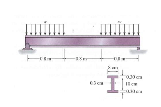
The steel beam has the configuration, loading pattern and cross-sectional area shown in Figure 8.
Assuming w = 5 kN/m, determine:
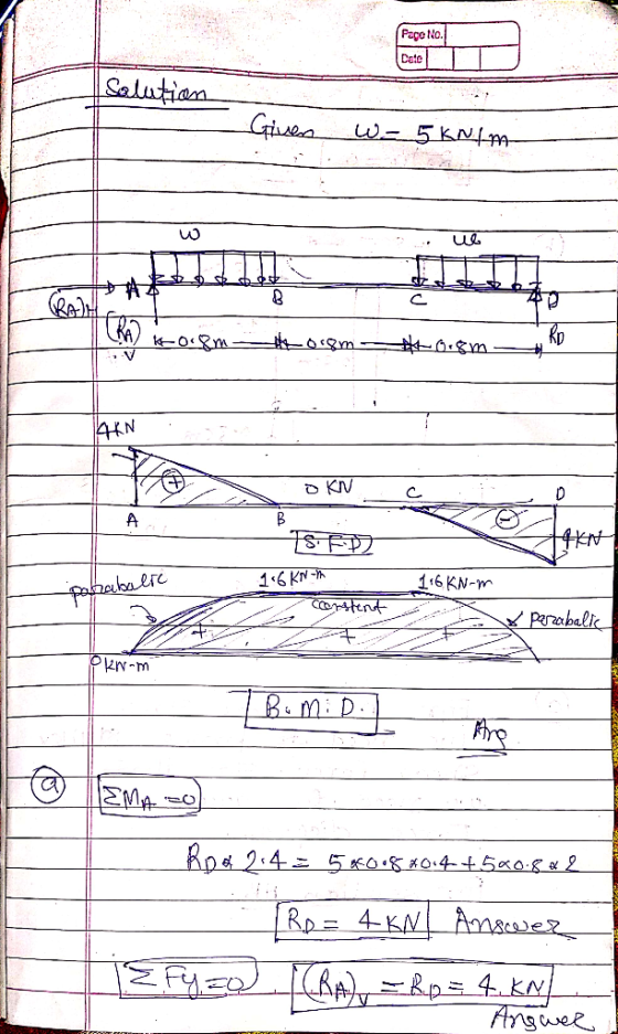
a) the reactions at each end of the beam
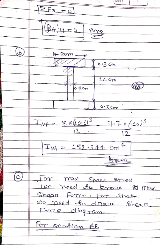
b) the second moment of area of the section about the relevant axis of bending
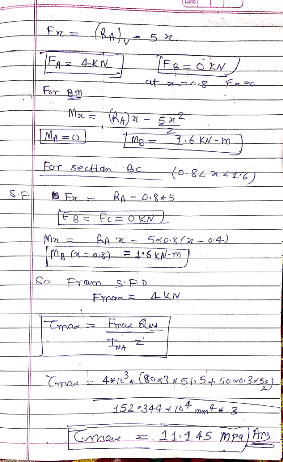
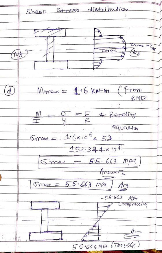
c) the maximum shear stress and associated distribution of shear stresses in the beam
d) the maximum bending stress and distribution of bending stresses in the beam
Homework Answers
Add Answer to:
The steel beam has the configuration, loading pattern and cross-sectional area shown in Figure 8. Assuming w = 5 kN/m, d...
The beam has the cross-sectional area shown. If the loading intensity o 25 kN/m and the...
 The beam has the cross-sectional area shown. If the loading intensity o 25 kN/m and the length of the beam L is 3 m, answer the questions that follow: 0 TALALRATEATAITTAAAAATTAAAAAL 100 mm 25 mm 25 mm 75 mm 75 mm 25 mm Determine the maximumm bending moment in the bearm in [kNm] Determine the position of the neutral axis, as a distance in [mm] measured from the bottom of the beam i.e. determine V Determine the area moment of...
The steel beam has the cross-sectional area shown. (Figure 1) Part A If w = 5.5...
 The steel beam has the cross-sectional area shown. (Figure 1) Part A If w = 5.5 kip/ft, determine the absolute maximum bending stress in the beam. VO AEDIT vec ? ksi Submit Request Answer < Return to Assignment Provide Feedback Figure < 1 of 1 8 ft 8 ft 8 ft 8 in. 10.30 in. H 0.3 in. 10 in. -0.30 in.
Q4. (20 pts) A kN/m BEN. X mm The beam has the cross-sectional area and loaded...
 Q4. (20 pts) A kN/m BEN. X mm The beam has the cross-sectional area and loaded as shown. Draw the bending and shear force diagrams. Find the maximum bending stress in the beam. التسعي HO Z mm Y mm 3 m Z mm A=40 X=75 B=25 Y=125 Z=10
Consider the beam and loading shown. The cross-sectional area is rectangular which measures 200 mm x...
 Consider the beam and loading shown. The cross-sectional area is rectangular which measures 200 mm x 400 mm. What is the maximum bending stress, fbmax in MPa ? Use two decimal places. 10 kN 50 kNm с B 2m 3 m
Consider the beam and loading shown. The cross-sectional area is rectangular which measures 200 mm x...
 Consider the beam and loading shown. The cross-sectional area is
rectangular which measures 200 mm x 400 mm. What is the
maximum bending stress, fbmax in MPa ? Use two decimal
places.
y 10 kN 50 kNm A с X +B 2m 3 m
Consider the beam and loading shown. The cross-sectional area is
rectangular which measures 200 mm x 400 mm. What is the
maximum bending stress, fbmax in MPa ? Use two decimal
places.
y 10 kN 50 kNm A с X +B 2m 3 m
The overhanging beam has the cross-sectional area shown in Fig. below. Determine the maximum bending stress...
 The overhanging beam has the cross-sectional area shown in Fig. below. Determine the maximum bending stress in the beam and draw the stress distribution over the cross section. 8 kN 25 mm 2kN/m 1150 mm IT 250 mm 25 mm Im4m
4. A T-shaped cross-sectional beam is loaded as shown in the figure. Determine the following a....
 4. A T-shaped cross-sectional beam is loaded as shown in the figure. Determine the following a. Sketch the internal shear force and bending moment diagrams for the beam. b. Calculate the maximum magnitude of the bending stress. Indicate where this occurs on the cross-section and along the length of the beam. c. Calculate the transverse shearing stress at the centroid of the cross-section using the maximum magnitude of the transverse shear force. - 200 mm 8 KN 1.5 kN/m 20...
The A992 steel rod is subjected to the loading shown. If the cross-sectional area of the...
 The A992 steel rod is
subjected to the loading shown. If the cross-sectional area of the
rod is 100 mm2. Neglect the size of the couplings at B and C. The
elastic modulus and yield stress of A992 steel is 200 GPa and 345
MPa respectively. Determine the displacement of B and A with
respect to point D. (Preserve 2 significant digits after the
decimal point.)
QUESTION 1 The 1992 steel rod is subjected to the loading shown. If the...
The A992 steel rod is
subjected to the loading shown. If the cross-sectional area of the
rod is 100 mm2. Neglect the size of the couplings at B and C. The
elastic modulus and yield stress of A992 steel is 200 GPa and 345
MPa respectively. Determine the displacement of B and A with
respect to point D. (Preserve 2 significant digits after the
decimal point.)
QUESTION 1 The 1992 steel rod is subjected to the loading shown. If the...
As shown in Figure 8, the structural member (beam) is 7m long, carries a 2 kN point load, a 1.2 kN/m uniformly distribu...
 As shown in Figure 8, the structural member (beam) is 7m long, carries a 2 kN point load, a 1.2 kN/m uniformly distributed load and is supported at points A and B. The beam is constructed from two pieces of steel plate (2 at 80mm x 8mm) that are welded together with 3mm welds. Section properties for the beam are also listed. Given the support reactions as RAv 5.8 kN and RBv 2.2 kN, as well as the shear force...
The steel beam has the cross-sectional area shown, If o-30KN/m, determine the Problem 4 maximum bending...
 The steel beam has the cross-sectional area shown, If o-30KN/m, determine the Problem 4 maximum bending stress in the beam. Wo 3 m 3 m 200 mm 6 18 6 mm 30x8- 01N 300 mm 6 mm 6 mm
 The beam has the cross-sectional area shown. If the loading intensity o 25 kN/m and the length of the beam L is 3 m, answer the questions that follow: 0 TALALRATEATAITTAAAAATTAAAAAL 100 mm 25 mm 25 mm 75 mm 75 mm 25 mm Determine the maximumm bending moment in the bearm in [kNm] Determine the position of the neutral axis, as a distance in [mm] measured from the bottom of the beam i.e. determine V Determine the area moment of...
 The steel beam has the cross-sectional area shown. (Figure 1) Part A If w = 5.5 kip/ft, determine the absolute maximum bending stress in the beam. VO AEDIT vec ? ksi Submit Request Answer < Return to Assignment Provide Feedback Figure < 1 of 1 8 ft 8 ft 8 ft 8 in. 10.30 in. H 0.3 in. 10 in. -0.30 in.
 Q4. (20 pts) A kN/m BEN. X mm The beam has the cross-sectional area and loaded as shown. Draw the bending and shear force diagrams. Find the maximum bending stress in the beam. التسعي HO Z mm Y mm 3 m Z mm A=40 X=75 B=25 Y=125 Z=10
 Consider the beam and loading shown. The cross-sectional area is rectangular which measures 200 mm x 400 mm. What is the maximum bending stress, fbmax in MPa ? Use two decimal places. 10 kN 50 kNm с B 2m 3 m
 Consider the beam and loading shown. The cross-sectional area is
rectangular which measures 200 mm x 400 mm. What is the
maximum bending stress, fbmax in MPa ? Use two decimal
places.
y 10 kN 50 kNm A с X +B 2m 3 m
Consider the beam and loading shown. The cross-sectional area is
rectangular which measures 200 mm x 400 mm. What is the
maximum bending stress, fbmax in MPa ? Use two decimal
places.
y 10 kN 50 kNm A с X +B 2m 3 m
 The overhanging beam has the cross-sectional area shown in Fig. below. Determine the maximum bending stress in the beam and draw the stress distribution over the cross section. 8 kN 25 mm 2kN/m 1150 mm IT 250 mm 25 mm Im4m
 4. A T-shaped cross-sectional beam is loaded as shown in the figure. Determine the following a. Sketch the internal shear force and bending moment diagrams for the beam. b. Calculate the maximum magnitude of the bending stress. Indicate where this occurs on the cross-section and along the length of the beam. c. Calculate the transverse shearing stress at the centroid of the cross-section using the maximum magnitude of the transverse shear force. - 200 mm 8 KN 1.5 kN/m 20...
 The A992 steel rod is
subjected to the loading shown. If the cross-sectional area of the
rod is 100 mm2. Neglect the size of the couplings at B and C. The
elastic modulus and yield stress of A992 steel is 200 GPa and 345
MPa respectively. Determine the displacement of B and A with
respect to point D. (Preserve 2 significant digits after the
decimal point.)
QUESTION 1 The 1992 steel rod is subjected to the loading shown. If the...
The A992 steel rod is
subjected to the loading shown. If the cross-sectional area of the
rod is 100 mm2. Neglect the size of the couplings at B and C. The
elastic modulus and yield stress of A992 steel is 200 GPa and 345
MPa respectively. Determine the displacement of B and A with
respect to point D. (Preserve 2 significant digits after the
decimal point.)
QUESTION 1 The 1992 steel rod is subjected to the loading shown. If the...
 As shown in Figure 8, the structural member (beam) is 7m long, carries a 2 kN point load, a 1.2 kN/m uniformly distributed load and is supported at points A and B. The beam is constructed from two pieces of steel plate (2 at 80mm x 8mm) that are welded together with 3mm welds. Section properties for the beam are also listed. Given the support reactions as RAv 5.8 kN and RBv 2.2 kN, as well as the shear force...
 The steel beam has the cross-sectional area shown, If o-30KN/m, determine the Problem 4 maximum bending stress in the beam. Wo 3 m 3 m 200 mm 6 18 6 mm 30x8- 01N 300 mm 6 mm 6 mm
Most questions answered within 3 hours.
-
The extent to which assets are financed by borrowed funds and
other liabilities is indicated by:...
asked 40 minutes ago -
Explain in detail
Germany is the fifth largest economy
explain what goods and services Germany specializes...
asked 55 minutes ago -
The density of platinum is 21.45 g/mL. If a cube of platinum
with a mass of...
asked 1 hour ago -
Accounts Receivable
Sales
A/R Posting
Extended Sales Invoice
Packing Slip
Compare invoice to packing slip 2...
asked 1 hour ago -
Michaella, age 23, is a full-time law student and is claimed by
her parents as a...
asked 1 hour ago -
Why are polymers not typically casted into products?
asked 1 hour ago -
When rolling a die 129 times, what is the probability of rolling
a 6 no more...
asked 1 hour ago -
4. A call option currently sells for $7.75. It has a strike
price of $85 and...
asked 1 hour ago -
1.
You need to prepare 10.0 liters of an acid aqueous solution with a
pH of...
asked 1 hour ago -
Along an aggregate supply curve, if the level of output is less
than the natural level...
asked 1 hour ago -
By 2025, annual consumption in emerging markets will total $30
trillion and contribute more than ________...
asked 1 hour ago -
At what point does reformation cease to be a viable option for
those who are oppressed...
asked 1 hour ago