can you calculating this question and explain why? thanks

Typical time curves type CO-8 over current relay 50-60 hertz Current tap setting A 6 0.5 0.6 08 1.0 1,5 2.0 2.5 11 time dial setting 10 3.5 6 3 2 7 10 12 0.5 3 4 5 6 7 8 10 12 1416 20 2 1 Relay input current in multiples of current tap setting Figure 4 Relay operating time (seconds)
Homework Answers
Weakness of the existing overcurrent protection schemes
Existing protection schemes are self-contained entities that use independent local measurement chains to deliver their functionality. However, the increasing complexity of power systems has given rise to System Integrity Protection Schemes (SIPS), which use wide area measurements to deliver more complex functionality.
The measurements used by each of protection systems will vary significantly in terms of the type of measurement, the acceptable delay, the required reporting rate, the required resolution and the required accuracy.
SIPS are designed to protect the system from this specific set of contingencies using a set of pre-determined actions that are designed based on offline system studies. These actions will be executed when a specific set of input conditions are satisfied . For a scheme to be classed as a SIPS the actions implemented must go beyond simply isolating the faulted elements.
The conditions required to trigger a SIPS and cause it to operate can include events (e.g. the loss of a line), the system response (e.g. the measured frequency being below a threshold), or a combination thereof. Furthermore, most SIPS are armed by one condition and then triggered by another condition. The use of SIPS is now a worldwide practice [21] and an ever increasing number of these schemes are being designed and implemented
Add Answer to:
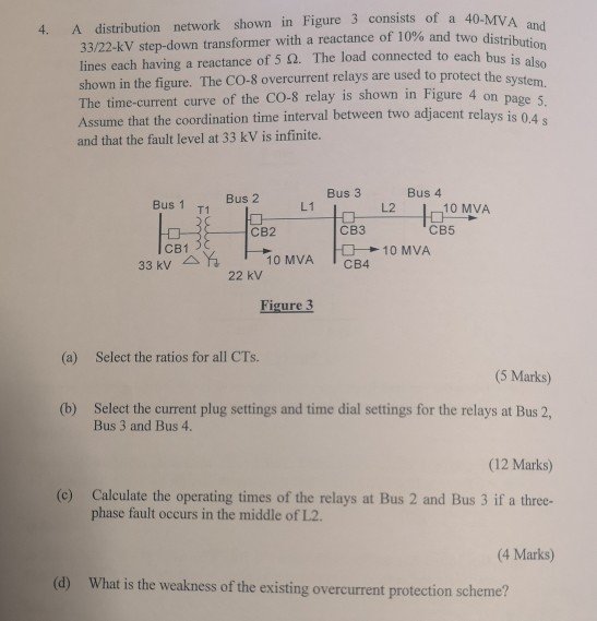
can you calculating this question and explain why? thanks A distribution network shown in Figure 3 consists of a 40-MV...
Part B (20 marks) Figure 2 shows a three phase 22kV, 50Hz radial system, which is to be protected by two inverse- time...
 Part B (20 marks) Figure 2 shows a three phase 22kV, 50Hz radial system, which is to be protected by two inverse- time over-current relays B1 and B2. The maximum loads for this system are L 6 MVA, and L2- 5 MVA. The maximum fault currents at bus 1 and bus 2 are 1500A and 1000A respectively. The minimum fault currents at bus 1 and bus 2 are 900A and 650A respectively The line currents are measured using current transformers...
can you calculating this question and explain why? thanks The ratings and sequence reactances of the components for...
 can you calculating this question and explain why?
thanks
The ratings and sequence reactances of the components for the power system shown in Figure 2 are given in Table 1. The pre-fault voltage is 1/0° per unit (pu). Bus 8 L3 Bus 1 T1 Bus 4 T2 Bus 2 Bus 5 L1 L2 G1 Bus 3 T3 Bus 7 Bus 6 D.6975 Figure Draw the per unit impedance sequence networks and determine the per unit (a) Thevenin impedances of the...
can you calculating this question and explain why?
thanks
The ratings and sequence reactances of the components for the power system shown in Figure 2 are given in Table 1. The pre-fault voltage is 1/0° per unit (pu). Bus 8 L3 Bus 1 T1 Bus 4 T2 Bus 2 Bus 5 L1 L2 G1 Bus 3 T3 Bus 7 Bus 6 D.6975 Figure Draw the per unit impedance sequence networks and determine the per unit (a) Thevenin impedances of the...
A distribution board distributes energy to various items of plant via an installation which has a...
 Step by step precise and concise full solution please
A distribution board distributes energy to various items of plant via an installation which has a high voltage (H.V.) panel, a low voltage (L.V) panel and a transformer. The details are as follows: The H.V. panel obtains a 3-phase supply at 11 kV. The transformer circuit-breaker is equipped with 75/5A current transformers which feed a very inverse 3-poles overcurrent relay of 5-A rating. The transformer has a rating of 1000 kVA...
Step by step precise and concise full solution please
A distribution board distributes energy to various items of plant via an installation which has a high voltage (H.V.) panel, a low voltage (L.V) panel and a transformer. The details are as follows: The H.V. panel obtains a 3-phase supply at 11 kV. The transformer circuit-breaker is equipped with 75/5A current transformers which feed a very inverse 3-poles overcurrent relay of 5-A rating. The transformer has a rating of 1000 kVA...
select one Best match 11) A 12 kV radial system is given below, Assuming using relay...
 select one Best match
11) A 12 kV radial system is given below, Assuming using relay CO-7, 3 cycles breaker operation time and 0.5 second coordination time delay, what are the best settings to protect the system shown below: (10 points) 12 kV Typical time curves ype Co-7 C.T.R-400/5 C.T.R-200/5 Current tap settings: 4.5,6,78,10,12 amperes 4 MVA Isc-1.6 kA 4 MVA Isc-1.2 kA Time dial TS1 TDS1 TS2 TDS2 A) 51/252 B) 41/24 C) 51/25 D) 41/24 2 4 5...
select one Best match
11) A 12 kV radial system is given below, Assuming using relay CO-7, 3 cycles breaker operation time and 0.5 second coordination time delay, what are the best settings to protect the system shown below: (10 points) 12 kV Typical time curves ype Co-7 C.T.R-400/5 C.T.R-200/5 Current tap settings: 4.5,6,78,10,12 amperes 4 MVA Isc-1.6 kA 4 MVA Isc-1.2 kA Time dial TS1 TDS1 TS2 TDS2 A) 51/252 B) 41/24 C) 51/25 D) 41/24 2 4 5...
18. The primary conductor in Figure 10.2 is one phase of a three-phase trans- mission line operat...
 18. The primary conductor in Figure 10.2 is one phase of a three-phase trans- mission line operating at 345 kV, 700 MVA, 0.95 power factor lagging. The CT ratio is 1200:5, and the VT ratio is 3000:1. Determine the CT second- ary current and the VT secondary voltage V. Assume zero CT error. A CO-8 relay with a current tap setting of 5 amperes is used with the 100:5 CT in Example 10.1. The CT secondary current I' is the...
Please solve the question properly & detailed. 29.A radial 11-kV distribution feeder connected to the grid...
 Please solve the question properly & detailed.
29.A radial 11-kV distribution feeder connected to the grid system is shown in FIGURE Q4. SUB-Z has undergone protection refurbishment project involving current transformer (CT) size. Overcurrent plug setting is 100% and earthfault plug setting is 10% of the CT ratio for both relays B and C. No grading margin is required between relay A and B. All relays use the Inverse Definite Minimum Time (IDMT) normal inverse curve. Propose the overcurrent and...
Please solve the question properly & detailed.
29.A radial 11-kV distribution feeder connected to the grid system is shown in FIGURE Q4. SUB-Z has undergone protection refurbishment project involving current transformer (CT) size. Overcurrent plug setting is 100% and earthfault plug setting is 10% of the CT ratio for both relays B and C. No grading margin is required between relay A and B. All relays use the Inverse Definite Minimum Time (IDMT) normal inverse curve. Propose the overcurrent and...
A 7-bus power system with three generators, six transformers, and seven transmission lines is shown in...
 A 7-bus power system with three generators, six transformers, and seven transmission lines is shown in Figure Q1. The per-unit reactances for the generators and transfomers are based on their rated voltage and expressed in percentage. When a three-phase fault occurs at bus 5; three transmission lines, namely L4, L5, and L6, are disconnected from the power system. By taking the base apparent power of 100 MVA and the rated voltage of generator G1 as the reference, determine the per-unit...
QUESTION 4. A single-line diagram of a power system is shown in Figure Q3 below, where...
 QUESTION 4. A single-line diagram of a power system is shown in Figure Q3 below, where negative and zero-sequence reactances are also given. The neutrals of the generator and A-Y transformers are solidly grounded. The motor neutral is grounded through a reactance X.=0.05 per unit on the motor base. Prefault voltage is VF1.05<Oº per unit whereas prefault load current is zero. Take A-Y transformer phase shifts into consideration. M Line tool X, - X2 - 200 100 MVA X =...
Zone 1 Zone 3 Zone 2 Xice j1002 BE SO MW 0.8 pf lagging Vload =...
 Zone 1 Zone 3 Zone 2 Xice j1002 BE SO MW 0.8 pf lagging Vload = 30 kV Ti 50 MVA 11/132 kV X= 10% Tz 50 MVA 132/33 kV X=12% Figure 1 2. A 500 MVA, 20 kV, 50 Hz synchronous generator with reactances Xd" = 0.15, Xá = 0.24, Xo = 1.1 p.u. and time constant To = 0.035, Tó' = 2.0, TA = 0.2 seconds is connected to a circuit breaker. The generator is operating at 5%...
can you calculate this question and explain why? thanks The electromagnet system shown in Figure 1 is used to lift a...
 can you calculate this question and explain why?
thanks
The electromagnet system shown in Figure 1 is used to lift a section of steel channel. The coil has 2000 turns and a resistance of 2 Q. The dimensions of the magnetic system are shown in the figure. The air gap 'g' is 0.5 cm. The reluctances of the electromagnet and channel can be ignored. 4T x10 H/m. 2. The permeability of free space is Find the flux and flux density...
can you calculate this question and explain why?
thanks
The electromagnet system shown in Figure 1 is used to lift a section of steel channel. The coil has 2000 turns and a resistance of 2 Q. The dimensions of the magnetic system are shown in the figure. The air gap 'g' is 0.5 cm. The reluctances of the electromagnet and channel can be ignored. 4T x10 H/m. 2. The permeability of free space is Find the flux and flux density...
 Part B (20 marks) Figure 2 shows a three phase 22kV, 50Hz radial system, which is to be protected by two inverse- time over-current relays B1 and B2. The maximum loads for this system are L 6 MVA, and L2- 5 MVA. The maximum fault currents at bus 1 and bus 2 are 1500A and 1000A respectively. The minimum fault currents at bus 1 and bus 2 are 900A and 650A respectively The line currents are measured using current transformers...
 can you calculating this question and explain why?
thanks
The ratings and sequence reactances of the components for the power system shown in Figure 2 are given in Table 1. The pre-fault voltage is 1/0° per unit (pu). Bus 8 L3 Bus 1 T1 Bus 4 T2 Bus 2 Bus 5 L1 L2 G1 Bus 3 T3 Bus 7 Bus 6 D.6975 Figure Draw the per unit impedance sequence networks and determine the per unit (a) Thevenin impedances of the...
can you calculating this question and explain why?
thanks
The ratings and sequence reactances of the components for the power system shown in Figure 2 are given in Table 1. The pre-fault voltage is 1/0° per unit (pu). Bus 8 L3 Bus 1 T1 Bus 4 T2 Bus 2 Bus 5 L1 L2 G1 Bus 3 T3 Bus 7 Bus 6 D.6975 Figure Draw the per unit impedance sequence networks and determine the per unit (a) Thevenin impedances of the...
 Step by step precise and concise full solution please
A distribution board distributes energy to various items of plant via an installation which has a high voltage (H.V.) panel, a low voltage (L.V) panel and a transformer. The details are as follows: The H.V. panel obtains a 3-phase supply at 11 kV. The transformer circuit-breaker is equipped with 75/5A current transformers which feed a very inverse 3-poles overcurrent relay of 5-A rating. The transformer has a rating of 1000 kVA...
Step by step precise and concise full solution please
A distribution board distributes energy to various items of plant via an installation which has a high voltage (H.V.) panel, a low voltage (L.V) panel and a transformer. The details are as follows: The H.V. panel obtains a 3-phase supply at 11 kV. The transformer circuit-breaker is equipped with 75/5A current transformers which feed a very inverse 3-poles overcurrent relay of 5-A rating. The transformer has a rating of 1000 kVA...
 select one Best match
11) A 12 kV radial system is given below, Assuming using relay CO-7, 3 cycles breaker operation time and 0.5 second coordination time delay, what are the best settings to protect the system shown below: (10 points) 12 kV Typical time curves ype Co-7 C.T.R-400/5 C.T.R-200/5 Current tap settings: 4.5,6,78,10,12 amperes 4 MVA Isc-1.6 kA 4 MVA Isc-1.2 kA Time dial TS1 TDS1 TS2 TDS2 A) 51/252 B) 41/24 C) 51/25 D) 41/24 2 4 5...
select one Best match
11) A 12 kV radial system is given below, Assuming using relay CO-7, 3 cycles breaker operation time and 0.5 second coordination time delay, what are the best settings to protect the system shown below: (10 points) 12 kV Typical time curves ype Co-7 C.T.R-400/5 C.T.R-200/5 Current tap settings: 4.5,6,78,10,12 amperes 4 MVA Isc-1.6 kA 4 MVA Isc-1.2 kA Time dial TS1 TDS1 TS2 TDS2 A) 51/252 B) 41/24 C) 51/25 D) 41/24 2 4 5...
 18. The primary conductor in Figure 10.2 is one phase of a three-phase trans- mission line operating at 345 kV, 700 MVA, 0.95 power factor lagging. The CT ratio is 1200:5, and the VT ratio is 3000:1. Determine the CT second- ary current and the VT secondary voltage V. Assume zero CT error. A CO-8 relay with a current tap setting of 5 amperes is used with the 100:5 CT in Example 10.1. The CT secondary current I' is the...
 Please solve the question properly & detailed.
29.A radial 11-kV distribution feeder connected to the grid system is shown in FIGURE Q4. SUB-Z has undergone protection refurbishment project involving current transformer (CT) size. Overcurrent plug setting is 100% and earthfault plug setting is 10% of the CT ratio for both relays B and C. No grading margin is required between relay A and B. All relays use the Inverse Definite Minimum Time (IDMT) normal inverse curve. Propose the overcurrent and...
Please solve the question properly & detailed.
29.A radial 11-kV distribution feeder connected to the grid system is shown in FIGURE Q4. SUB-Z has undergone protection refurbishment project involving current transformer (CT) size. Overcurrent plug setting is 100% and earthfault plug setting is 10% of the CT ratio for both relays B and C. No grading margin is required between relay A and B. All relays use the Inverse Definite Minimum Time (IDMT) normal inverse curve. Propose the overcurrent and...
 A 7-bus power system with three generators, six transformers, and seven transmission lines is shown in Figure Q1. The per-unit reactances for the generators and transfomers are based on their rated voltage and expressed in percentage. When a three-phase fault occurs at bus 5; three transmission lines, namely L4, L5, and L6, are disconnected from the power system. By taking the base apparent power of 100 MVA and the rated voltage of generator G1 as the reference, determine the per-unit...
 QUESTION 4. A single-line diagram of a power system is shown in Figure Q3 below, where negative and zero-sequence reactances are also given. The neutrals of the generator and A-Y transformers are solidly grounded. The motor neutral is grounded through a reactance X.=0.05 per unit on the motor base. Prefault voltage is VF1.05<Oº per unit whereas prefault load current is zero. Take A-Y transformer phase shifts into consideration. M Line tool X, - X2 - 200 100 MVA X =...
 Zone 1 Zone 3 Zone 2 Xice j1002 BE SO MW 0.8 pf lagging Vload = 30 kV Ti 50 MVA 11/132 kV X= 10% Tz 50 MVA 132/33 kV X=12% Figure 1 2. A 500 MVA, 20 kV, 50 Hz synchronous generator with reactances Xd" = 0.15, Xá = 0.24, Xo = 1.1 p.u. and time constant To = 0.035, Tó' = 2.0, TA = 0.2 seconds is connected to a circuit breaker. The generator is operating at 5%...
 can you calculate this question and explain why?
thanks
The electromagnet system shown in Figure 1 is used to lift a section of steel channel. The coil has 2000 turns and a resistance of 2 Q. The dimensions of the magnetic system are shown in the figure. The air gap 'g' is 0.5 cm. The reluctances of the electromagnet and channel can be ignored. 4T x10 H/m. 2. The permeability of free space is Find the flux and flux density...
can you calculate this question and explain why?
thanks
The electromagnet system shown in Figure 1 is used to lift a section of steel channel. The coil has 2000 turns and a resistance of 2 Q. The dimensions of the magnetic system are shown in the figure. The air gap 'g' is 0.5 cm. The reluctances of the electromagnet and channel can be ignored. 4T x10 H/m. 2. The permeability of free space is Find the flux and flux density...
Most questions answered within 3 hours.
-
For the reaction CaI2+2AgNO3⟶2AgI+Ca(NO3)2 how many grams of
silver iodide, AgI, are produced from 56.5 g...
asked 41 seconds ago -
Write an equation for hydrolysis via acid catalysis.
Using ethyl acetate, ethyl benzoate, ethyl formate or...
asked 8 minutes ago -
Only one graph is needed.
(a) Draw a Supply Curve and the Demand Curve for the...
asked 11 minutes ago -
Fill in the blanks and please show how you arrived at numerical
answers
. The...
asked 11 minutes ago -
91. If the half – life of a sample of radioactive
material is 60 days, what...
asked 18 minutes ago -
White light (380nm-750nm) strikes a diffraction grating (420
lines/mm) at normal incidence. What is the highest-order...
asked 28 minutes ago -
1) Explain what is meant by a good being "excludable."?
2) Explain what is meant by...
asked 27 minutes ago -
I need help with this question:
Describe in detail at least two factors that stimulated American...
asked 34 minutes ago -
Calculate the Boyle temperature for helium assuming it follows
the Berthelot equation of state.
asked 35 minutes ago -
Summarize Strategic Corporate Social Responsibility, 4th edition
2017 book, chapter one and two.
asked 35 minutes ago -
1. If the standard deviations for return on stock A and stock B
are 28% and...
asked 50 minutes ago -
Please use python to explain.
Assume that the variables x and
y refer to strings. Write...
asked 57 minutes ago