
Homework Answers


Add Answer to:
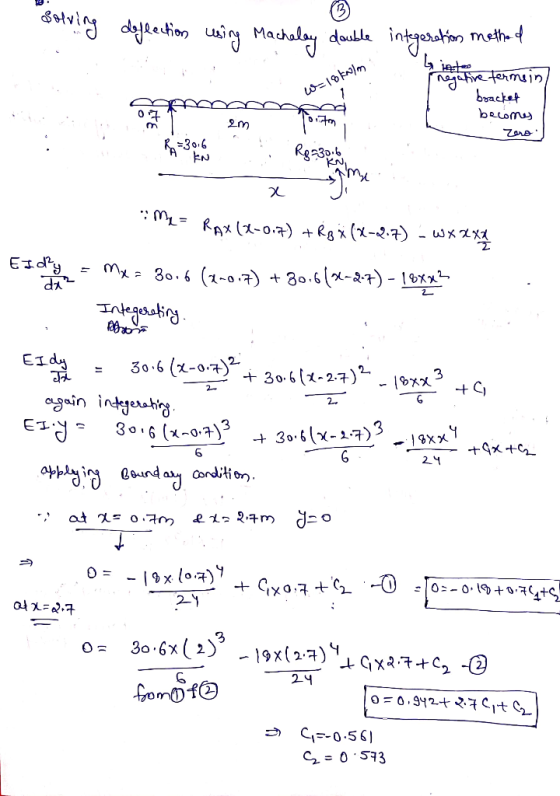
The below wooden double overhanging beam is under a uniformly distributed load W. The wood is...
PLESAE CONTINUE FROM C,D IF you consider the whole question to be too long thanks here...
 PLESAE
CONTINUE FROM C,D IF you consider the whole question to be too long
thanks
here are some support information
The below wooden double overhanging beam is under a uniformly distributed load w. The wood is weak along the orientation of the grain (or wood cell fibres) that makes an angle of 30° with the horizontal (see figure). The maximum shear stress on a plane parallel to the grain that the wood can sustain is tmax = 5 MPa, and...
PLESAE
CONTINUE FROM C,D IF you consider the whole question to be too long
thanks
here are some support information
The below wooden double overhanging beam is under a uniformly distributed load w. The wood is weak along the orientation of the grain (or wood cell fibres) that makes an angle of 30° with the horizontal (see figure). The maximum shear stress on a plane parallel to the grain that the wood can sustain is tmax = 5 MPa, and...
An overhanging steel beam is used to carry a uniformly distributed load over a 2-metre length as shown. The yield stress of steel is ơyield-350 MPa. Check if the cross section of the beam at section...
 An overhanging steel beam is used to carry a uniformly distributed load over a 2-metre length as shown. The yield stress of steel is ơyield-350 MPa. Check if the cross section of the beam at section a-a is safe against yielding, (a) using the maximum distortion energy criterion (Von Mises criterion) (b) using the maximum shear stress criterion (Tresca) 15 mm w-12 kN/m 15 mm 120 mm 2000 mm 15 mm 3000 mm 3000 mm 6000 mm 60 mm
An...
An overhanging steel beam is used to carry a uniformly distributed load over a 2-metre length as shown. The yield stress of steel is ơyield-350 MPa. Check if the cross section of the beam at section a-a is safe against yielding, (a) using the maximum distortion energy criterion (Von Mises criterion) (b) using the maximum shear stress criterion (Tresca) 15 mm w-12 kN/m 15 mm 120 mm 2000 mm 15 mm 3000 mm 3000 mm 6000 mm 60 mm
An...
If the overhanging beam is made of wood having the allowable tensile and compressive stresses of...
 If the overhanging beam is made of wood having the allowable
tensile and compressive stresses
of (?all)t = 4 MPa and (?all)c = 5 MPa, determine the maximum
concentrated force P that can
applied at the free end. Draw the shear, moment diagrams and sketch
the stress distribution
acting over the cross section. The material is wood select
structural grade (Douglas Fir) with a
specific gravity of 0.47 Mg/m^3.
If the overhanging beam is made of wood having the allowable
tensile and compressive stresses
of (?all)t = 4 MPa and (?all)c = 5 MPa, determine the maximum
concentrated force P that can
applied at the free end. Draw the shear, moment diagrams and sketch
the stress distribution
acting over the cross section. The material is wood select
structural grade (Douglas Fir) with a
specific gravity of 0.47 Mg/m^3.
The simply-supported beam having I-beam cross-section as shown in figure is to carry a uniformly distributed...
 The simply-supported beam having I-beam cross-section as shown in figure is to carry a uniformly distributed load over its entire 1.2m length. Specify the maximum allowable load if the beam is made from malleable iron, ASTM A220, class 80002. The allowable tensile stress is 164 MPa and allowable compressive stress is 412 MPa. The centroid of the section is located at 35 mm from the bottom and moment of inertia are Ix = 2.66 x 10 mm". (a) Draw loading...
(Q2) For the shown beam, a uniformly distributed load is applied across the beam length. The...
 (Q2) For the shown beam, a uniformly distributed load is applied across the beam length. The beam cross section is symmetrical. The beam length and cross-sectional dimensions are shown in figure. 40 mm B С 300 mm 10 N/m N A 40 mm 300 mm 40 mm 500 mm 1- Plot the Shear Force Distribution (with values) 2- Plot the Bending Moment Distribution (with values) 3. Determine the maximum Moment value and indicate the most critical section 4- Calculate the...
Problem 3 (19 points): A simply supported beam ABCD carries a uniformly distributed load, w, and...
 Problem 3 (19 points): A simply supported beam ABCD carries a uniformly distributed load, w, and a concentrated load, F, as shown in the figure. All the dimensions are given in the figure, and the weight of the beam is neglected a) Draw the free body diagram for the beam, showing all the applied and reaction forces. Find the reaction forces F=14 kN .6m b) Give the expression for the shear force, V- V(x), and the bending moment M M(x),...
The beam having a cross-section as shown is subjected to the distributed load w (1) Calculate...
 The beam having a cross-section as shown is subjected to the distributed load w (1) Calculate the moment of inertia, I (2) If the allowable maximum normal stress ơmax-20 MPa, determine the largest distributed load 5. w. (3) If w 1.5 kN/m, determine the maximum bending stress in the beam. Sketch the stress distribution acting over the cross-section. 100 mm 50mm 120 mm 3 m50 mm 3 m
scenes M4.3 Load capacity of beam-strut structure The structure supports a distributed load of w. The...
 scenes M4.3 Load capacity of beam-strut structure The structure supports a distributed load of w. The limiting stress in rod (1) is 380 MPa, and the limiting stress in each pin is 220 MPa. If the minimum factor of safety for the structure is 1.60, determine the 2 m maximum distributed load magnitude w that may be applied to the structure plus the stresses in the rod and pins at the maximum w. 14-mm-diam. pin Home Chap 1. Stress Chap...
A wood beam (1) is reinforced on its lower surface by a steel plate (2) as...
 A wood beam (1) is reinforced on its lower surface by a steel
plate (2) as shown in the figure. Dimensions of the cross section
are b 1 = 220 mm , d = 385 mm , b 2 = 190 mm , and t = 25 mm . The
elastic moduli of the wood and steel are E 1 = 12.5 GPa and E 2 =
200 GPa , respectively. The allowable bending stresses of the wood
and steel...
A wood beam (1) is reinforced on its lower surface by a steel
plate (2) as shown in the figure. Dimensions of the cross section
are b 1 = 220 mm , d = 385 mm , b 2 = 190 mm , and t = 25 mm . The
elastic moduli of the wood and steel are E 1 = 12.5 GPa and E 2 =
200 GPa , respectively. The allowable bending stresses of the wood
and steel...
M4.3 Load capacity of beam-strut structure scenes The structure supports a distributed load of w. The...
 M4.3 Load capacity of beam-strut structure scenes The structure supports a distributed load of w. The limiting stress in rod (1) is 330 MPa, and the limiting stress in each pin is 200 MPa. If the minimum factor of safety for the structure is 2.20, determine the maximum distributed load magnitude w that may be applied to the struct the stresses in the rod and pins at the maximum w. 1 m 14-mm-diam. pin e plus double shear 12-mm-diam. rod...
 PLESAE
CONTINUE FROM C,D IF you consider the whole question to be too long
thanks
here are some support information
The below wooden double overhanging beam is under a uniformly distributed load w. The wood is weak along the orientation of the grain (or wood cell fibres) that makes an angle of 30° with the horizontal (see figure). The maximum shear stress on a plane parallel to the grain that the wood can sustain is tmax = 5 MPa, and...
PLESAE
CONTINUE FROM C,D IF you consider the whole question to be too long
thanks
here are some support information
The below wooden double overhanging beam is under a uniformly distributed load w. The wood is weak along the orientation of the grain (or wood cell fibres) that makes an angle of 30° with the horizontal (see figure). The maximum shear stress on a plane parallel to the grain that the wood can sustain is tmax = 5 MPa, and...
 An overhanging steel beam is used to carry a uniformly distributed load over a 2-metre length as shown. The yield stress of steel is ơyield-350 MPa. Check if the cross section of the beam at section a-a is safe against yielding, (a) using the maximum distortion energy criterion (Von Mises criterion) (b) using the maximum shear stress criterion (Tresca) 15 mm w-12 kN/m 15 mm 120 mm 2000 mm 15 mm 3000 mm 3000 mm 6000 mm 60 mm
An...
An overhanging steel beam is used to carry a uniformly distributed load over a 2-metre length as shown. The yield stress of steel is ơyield-350 MPa. Check if the cross section of the beam at section a-a is safe against yielding, (a) using the maximum distortion energy criterion (Von Mises criterion) (b) using the maximum shear stress criterion (Tresca) 15 mm w-12 kN/m 15 mm 120 mm 2000 mm 15 mm 3000 mm 3000 mm 6000 mm 60 mm
An...
 If the overhanging beam is made of wood having the allowable
tensile and compressive stresses
of (?all)t = 4 MPa and (?all)c = 5 MPa, determine the maximum
concentrated force P that can
applied at the free end. Draw the shear, moment diagrams and sketch
the stress distribution
acting over the cross section. The material is wood select
structural grade (Douglas Fir) with a
specific gravity of 0.47 Mg/m^3.
If the overhanging beam is made of wood having the allowable
tensile and compressive stresses
of (?all)t = 4 MPa and (?all)c = 5 MPa, determine the maximum
concentrated force P that can
applied at the free end. Draw the shear, moment diagrams and sketch
the stress distribution
acting over the cross section. The material is wood select
structural grade (Douglas Fir) with a
specific gravity of 0.47 Mg/m^3.
 The simply-supported beam having I-beam cross-section as shown in figure is to carry a uniformly distributed load over its entire 1.2m length. Specify the maximum allowable load if the beam is made from malleable iron, ASTM A220, class 80002. The allowable tensile stress is 164 MPa and allowable compressive stress is 412 MPa. The centroid of the section is located at 35 mm from the bottom and moment of inertia are Ix = 2.66 x 10 mm". (a) Draw loading...
 (Q2) For the shown beam, a uniformly distributed load is applied across the beam length. The beam cross section is symmetrical. The beam length and cross-sectional dimensions are shown in figure. 40 mm B С 300 mm 10 N/m N A 40 mm 300 mm 40 mm 500 mm 1- Plot the Shear Force Distribution (with values) 2- Plot the Bending Moment Distribution (with values) 3. Determine the maximum Moment value and indicate the most critical section 4- Calculate the...
 Problem 3 (19 points): A simply supported beam ABCD carries a uniformly distributed load, w, and a concentrated load, F, as shown in the figure. All the dimensions are given in the figure, and the weight of the beam is neglected a) Draw the free body diagram for the beam, showing all the applied and reaction forces. Find the reaction forces F=14 kN .6m b) Give the expression for the shear force, V- V(x), and the bending moment M M(x),...
 The beam having a cross-section as shown is subjected to the distributed load w (1) Calculate the moment of inertia, I (2) If the allowable maximum normal stress ơmax-20 MPa, determine the largest distributed load 5. w. (3) If w 1.5 kN/m, determine the maximum bending stress in the beam. Sketch the stress distribution acting over the cross-section. 100 mm 50mm 120 mm 3 m50 mm 3 m
 scenes M4.3 Load capacity of beam-strut structure The structure supports a distributed load of w. The limiting stress in rod (1) is 380 MPa, and the limiting stress in each pin is 220 MPa. If the minimum factor of safety for the structure is 1.60, determine the 2 m maximum distributed load magnitude w that may be applied to the structure plus the stresses in the rod and pins at the maximum w. 14-mm-diam. pin Home Chap 1. Stress Chap...
 A wood beam (1) is reinforced on its lower surface by a steel
plate (2) as shown in the figure. Dimensions of the cross section
are b 1 = 220 mm , d = 385 mm , b 2 = 190 mm , and t = 25 mm . The
elastic moduli of the wood and steel are E 1 = 12.5 GPa and E 2 =
200 GPa , respectively. The allowable bending stresses of the wood
and steel...
A wood beam (1) is reinforced on its lower surface by a steel
plate (2) as shown in the figure. Dimensions of the cross section
are b 1 = 220 mm , d = 385 mm , b 2 = 190 mm , and t = 25 mm . The
elastic moduli of the wood and steel are E 1 = 12.5 GPa and E 2 =
200 GPa , respectively. The allowable bending stresses of the wood
and steel...
 M4.3 Load capacity of beam-strut structure scenes The structure supports a distributed load of w. The limiting stress in rod (1) is 330 MPa, and the limiting stress in each pin is 200 MPa. If the minimum factor of safety for the structure is 2.20, determine the maximum distributed load magnitude w that may be applied to the struct the stresses in the rod and pins at the maximum w. 1 m 14-mm-diam. pin e plus double shear 12-mm-diam. rod...
Most questions answered within 3 hours.
-
What is a population?
Select one:
a. All of the individual organisms belonging to the same...
asked 1 minute from now -
You have a yeast cell culture with a concentration of 5x10^4
cells/ml. If you dilute this...
asked 2 minutes ago -
In which direction the Reaction goes? Show detailed process.
SeO3 + 2ClO2. + 2H3O <---> Se...
asked 16 minutes ago -
Unexposed silver halides are removed from photographic film when
they react with sodium thiosulfate
(Na2S2O3, called...
asked 16 minutes ago -
A 0.3054 gram sample of the mineral chalcopyrite (CuFeS2)
yielded 0.6525 gram BaSO4 precipitate. What is...
asked 16 minutes ago -
An short-seller in Tesla is worried the latest management
earnings forecast is too aggressive and the...
asked 1 hour ago -
Question 3 (1 point)
Fill in the blank. Speed Car Rental company found that the tire...
asked 1 hour ago -
1. A copper wire is 26.61 cm long and weighs 1.265 g. The
density of copper...
asked 40 minutes ago -
Remember that a concept sketch consists of a sketch (or
series of sketches), labels, and complete...
asked 42 minutes ago -
on a newly discovered planet, the period of a pendulum with a
length of 2 m...
asked 44 minutes ago -
Why [M(CN)6] is not organometallic even it has metal
to carbon bond too
asked 51 minutes ago -
mstar electric has a bond issue outstanding that has a 20 year
life, a $1,000 par...
asked 58 minutes ago