

Homework Answers


![را بر 12 S-8 O=Tm (2 (28 53.01123 e-c EMC = asinox 5-8 - wx (5- 여 I 42857.66981 x sin ( 53-01/23] x5-5) -wx (5-8+13)? Q](http://img.homeworklib.com/questions/3fd4b3c0-25d9-11eb-86a6-a332ce514d0f.png?x-oss-process=image/resize,w_560)

Add Answer to:
scenes M4.3 Load capacity of beam-strut structure The structure supports a distributed load of w. The...
M4.3 Load capacity of beam-strut structure scenes The structure supports a distributed load of w. The...
 M4.3 Load capacity of beam-strut structure scenes The structure supports a distributed load of w. The limiting stress in rod (1) is 330 MPa, and the limiting stress in each pin is 200 MPa. If the minimum factor of safety for the structure is 2.20, determine the maximum distributed load magnitude w that may be applied to the struct the stresses in the rod and pins at the maximum w. 1 m 14-mm-diam. pin e plus double shear 12-mm-diam. rod...
M4.3 Load capacity of beam-strut structure scenes The structure supports a distributed load of w. The...
 M4.3 Load capacity of beam-strut structure scenes The structure supports a distributed load of w. The limiting stress in rod (1) is 340 MPa, and the limiting stress in each pin is 190 MPa. If the minimum factor of safety for the structure is 2.00, determine the maximum distributed load magnitude w that may be applied to the structure plus the stresses in the rod and pins at the maximum w. 3.1 m 24-mm-diam. pin double shear w (kN/m) 26-mm-diam....
A pin-connected beam AC shown in Figure is supported by 1.6m of strut BD. The beam is subjected t...
 A pin-connected beam AC shown in Figure is supported by 1.6m of strut BD. The beam is subjected to uniformly distributed load of 20 kN/m at 2.5m from A and an inclined concentrated load of 30 KN with 30℃ angle at respectively. The beam has a constant cross-sectional area of Abm = 0.004 m2 and the strut has a constant cross sectional area of Ast = 0.002 m2 respectively. The diameter of all pins is 20 mm. I. Determine the resultant...
Beam AB is supported as shown in the figure. Tie rod(1) has a diameter of...
 Beam AB is supported as shown in the figure. Tie rod
(1) has a diameter of 60 mm, and it is attached at B and C with 24 mm diameter double-shear pin connections. The pin
connection at A consists of a 37 mm diameter single-shear
pin. The pins at A, B, and C each have
an ultimate shear strength of 500 MPa, and tie rod (1) has a yield
strength of 280 MPa. A uniformly distributed load of w is applied
to...
Beam AB is supported as shown in the figure. Tie rod
(1) has a diameter of 60 mm, and it is attached at B and C with 24 mm diameter double-shear pin connections. The pin
connection at A consists of a 37 mm diameter single-shear
pin. The pins at A, B, and C each have
an ultimate shear strength of 500 MPa, and tie rod (1) has a yield
strength of 280 MPa. A uniformly distributed load of w is applied
to...
M8.16 The transformed-section method scenes 210 mm 28 mm E 160 GPa E=90 GPa 76 mm...
 M8.16 The transformed-section method scenes 210 mm 28 mm E 160 GPa E=90 GPa 76 mm K 240 mm y (mm) A composite beam cross section consists of two rectangular bars securely bonded together. The beam is subjected to a bending moment M = 20 kN-m that produces compression stress at H Determine: Oн (MPa) a) the vertical distance from K to the horizontal centroidal axis Ок (MPa) b) the bending stress produced at H c) the bending stress produced...
The A-36 W150x37.1 b that can be applied to the beam without causing the strut to...
 The A-36 W150x37.1 b that can be applied to the beam without causing the strut to buckle or the beam to exceed allowable shear stress. Take F.S. 2. (20 points) steel rod BC has a diameter of 50mm and is used as a strut to support the eam. Determine the maximum intensity w of the uniform distributed load sw 6 m 3 m
please show how they got the answers also please show how they found Qh becuse it...
 please show how they got the answers also please show how they
found Qh becuse it is not given.
scenes M15.2 Principal stresses in a tee beam The inverted tee shape is subjected to a transverse shear force of V = 110 kN and a bending moment of M = 50 kN-m, each acting in the directions shown. Determine the bending stress, the transverse shear stress magnitude, the principal stresses, and the maximum shear stress acting at location H. 14...
please show how they got the answers also please show how they
found Qh becuse it is not given.
scenes M15.2 Principal stresses in a tee beam The inverted tee shape is subjected to a transverse shear force of V = 110 kN and a bending moment of M = 50 kN-m, each acting in the directions shown. Determine the bending stress, the transverse shear stress magnitude, the principal stresses, and the maximum shear stress acting at location H. 14...
The below wooden double overhanging beam is under a uniformly distributed load W. The wood is...
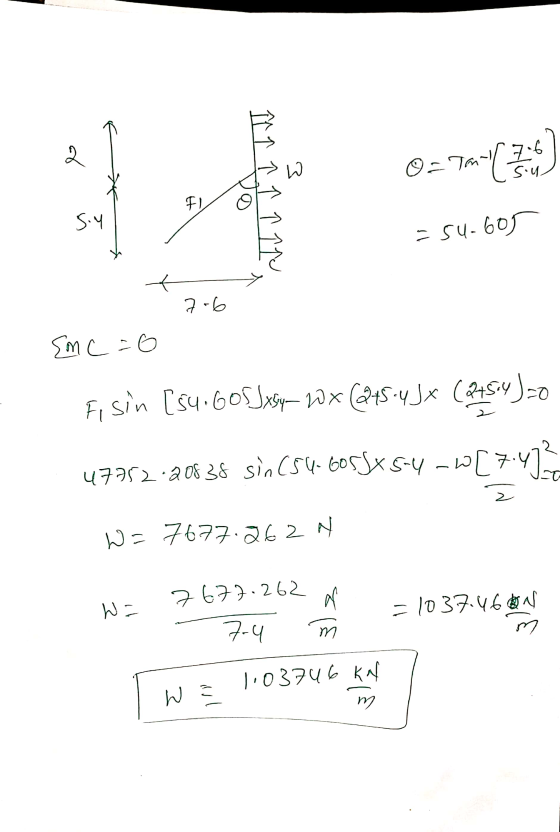
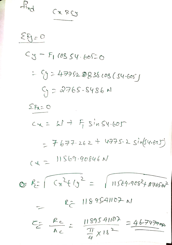
 The below wooden double overhanging beam is under a uniformly distributed load W. The wood is weak along the orientation of the grain (or wood cell fibres) that makes an angle of 30° with the horizontal (see figure). The maximum shear stress on a plane parallel to the grain that the wood can sustain is t,max = 5 MPa, and the maximum normal stress of wood is omax = 25 MPa. The Young modulus of this wood is E=15 GPa....
Beam AB is supported as shown in the figure. Tie rod (1) has a diameter of...
 Beam AB is supported as shown in the figure. Tie rod (1) has a diameter of 58 mm ,and it is attached at B and Cwith 24 mm diameter double-shear pin connections. The pin connection at A consists of a 40 mm diameter single-shear pin. The pins at A, B, and C each have an ultimate shear strength of 500 MPа ,and tie rod (1) has a yield strength of 280 МРPа . A uniformly distributed load of W is...
M5.5 Rod and post in series scenes Rod properties A- 340 mm2 E1 80 GPa A2-520...
 M5.5 Rod and post in series scenes Rod properties A- 340 mm2 E1 80 GPa A2-520 mm2 E2 160 GPa 65 kN F1 (kN 2000 mm 2800 mm A composite axial structure consists of two rods joined at flange B. Rods (1) and (2) are attached to rigid supports at A and C, respectively. kN ?i (MPa A concentrated load P is applied to flange B in the direction shown. Determine the internal forces and normal stresses in each rod....
 M4.3 Load capacity of beam-strut structure scenes The structure supports a distributed load of w. The limiting stress in rod (1) is 330 MPa, and the limiting stress in each pin is 200 MPa. If the minimum factor of safety for the structure is 2.20, determine the maximum distributed load magnitude w that may be applied to the struct the stresses in the rod and pins at the maximum w. 1 m 14-mm-diam. pin e plus double shear 12-mm-diam. rod...
 M4.3 Load capacity of beam-strut structure scenes The structure supports a distributed load of w. The limiting stress in rod (1) is 340 MPa, and the limiting stress in each pin is 190 MPa. If the minimum factor of safety for the structure is 2.00, determine the maximum distributed load magnitude w that may be applied to the structure plus the stresses in the rod and pins at the maximum w. 3.1 m 24-mm-diam. pin double shear w (kN/m) 26-mm-diam....
 Beam AB is supported as shown in the figure. Tie rod
(1) has a diameter of 60 mm, and it is attached at B and C with 24 mm diameter double-shear pin connections. The pin
connection at A consists of a 37 mm diameter single-shear
pin. The pins at A, B, and C each have
an ultimate shear strength of 500 MPa, and tie rod (1) has a yield
strength of 280 MPa. A uniformly distributed load of w is applied
to...
Beam AB is supported as shown in the figure. Tie rod
(1) has a diameter of 60 mm, and it is attached at B and C with 24 mm diameter double-shear pin connections. The pin
connection at A consists of a 37 mm diameter single-shear
pin. The pins at A, B, and C each have
an ultimate shear strength of 500 MPa, and tie rod (1) has a yield
strength of 280 MPa. A uniformly distributed load of w is applied
to...
 M8.16 The transformed-section method scenes 210 mm 28 mm E 160 GPa E=90 GPa 76 mm K 240 mm y (mm) A composite beam cross section consists of two rectangular bars securely bonded together. The beam is subjected to a bending moment M = 20 kN-m that produces compression stress at H Determine: Oн (MPa) a) the vertical distance from K to the horizontal centroidal axis Ок (MPa) b) the bending stress produced at H c) the bending stress produced...
 The A-36 W150x37.1 b that can be applied to the beam without causing the strut to buckle or the beam to exceed allowable shear stress. Take F.S. 2. (20 points) steel rod BC has a diameter of 50mm and is used as a strut to support the eam. Determine the maximum intensity w of the uniform distributed load sw 6 m 3 m
 please show how they got the answers also please show how they
found Qh becuse it is not given.
scenes M15.2 Principal stresses in a tee beam The inverted tee shape is subjected to a transverse shear force of V = 110 kN and a bending moment of M = 50 kN-m, each acting in the directions shown. Determine the bending stress, the transverse shear stress magnitude, the principal stresses, and the maximum shear stress acting at location H. 14...
please show how they got the answers also please show how they
found Qh becuse it is not given.
scenes M15.2 Principal stresses in a tee beam The inverted tee shape is subjected to a transverse shear force of V = 110 kN and a bending moment of M = 50 kN-m, each acting in the directions shown. Determine the bending stress, the transverse shear stress magnitude, the principal stresses, and the maximum shear stress acting at location H. 14...
 The below wooden double overhanging beam is under a uniformly distributed load W. The wood is weak along the orientation of the grain (or wood cell fibres) that makes an angle of 30° with the horizontal (see figure). The maximum shear stress on a plane parallel to the grain that the wood can sustain is t,max = 5 MPa, and the maximum normal stress of wood is omax = 25 MPa. The Young modulus of this wood is E=15 GPa....
 Beam AB is supported as shown in the figure. Tie rod (1) has a diameter of 58 mm ,and it is attached at B and Cwith 24 mm diameter double-shear pin connections. The pin connection at A consists of a 40 mm diameter single-shear pin. The pins at A, B, and C each have an ultimate shear strength of 500 MPа ,and tie rod (1) has a yield strength of 280 МРPа . A uniformly distributed load of W is...
 M5.5 Rod and post in series scenes Rod properties A- 340 mm2 E1 80 GPa A2-520 mm2 E2 160 GPa 65 kN F1 (kN 2000 mm 2800 mm A composite axial structure consists of two rods joined at flange B. Rods (1) and (2) are attached to rigid supports at A and C, respectively. kN ?i (MPa A concentrated load P is applied to flange B in the direction shown. Determine the internal forces and normal stresses in each rod....
Most questions answered within 3 hours.
-
The free energy change for the following reaction at 25 °C, when
[Sn2+] = 1.17 M...
asked 12 minutes ago -
An MNE is this kind of industry when competition in one country
is essentially independent of...
asked 1 hour ago -
. For this set of questions, determine what
proportion of a normal distribution is located betweeneach...
asked 2 hours ago -
A college student is employed as a door-to-door newspaper
salesman. Historical data suggests that the student...
asked 3 hours ago -
MATLAB HW 11 problem using Switch Case and Input commands
Write a script file that calculates...
asked 2 hours ago -
Considering gravitational time dilation, calculate the time that
passes in Earth’s surface while 1 hour passes...
asked 3 hours ago -
Minitab Problem: Take the Lake Hume June rainfall data and find
use the processes outlined in...
asked 4 hours ago -
X Company is trying to decide whether to continue using old
equipment to make Product A...
asked 4 hours ago -
IN PYTHON ONLY !! Program 2: Re-work
program #5 (WeeklyHours) from the previous assignment such that...
asked 5 hours ago -
The average length of time between arrivals at a turnpike
toll-booth is 26 seconds. What is...
asked 6 hours ago -
(a) A piston at 6.1 atm contains a gas that occupies a volume of
3.5 L....
asked 8 hours ago -
Please answer true or false. Words
cannot be changed or added in to make it true...
asked 7 hours ago