Refer to Fig. 10.7 in answering the following questions.FIGURE 10.7 (a) Image of a wire-bo...
Refer to Fig. 10.7 in answering the following questions.
FIGURE 10.7 (a) Image of a wire-bond template. (b) Result of processing with the +45° line detector mask in Fig. 10.6. (c) Zoomed view of the top left region of (b). (d) Zoomed view of the bottom right region of (b). (e) The image in (b) with all negative values set to zero. (f) All points (in white) whose values satisfied the condition g ≥ T, where g is the image in (e). (The points in (f) were enlarged to make them easier to see.)
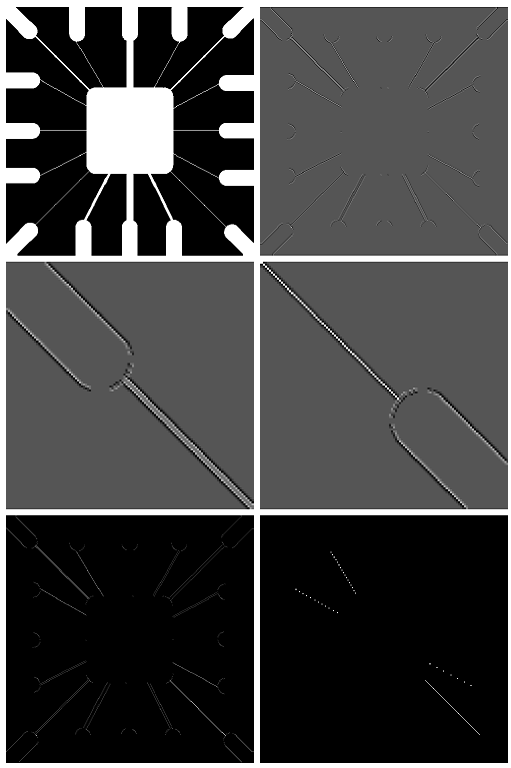
(a) Some of the lines joining the pads and center element in Fig. 10.7(e) are single lines, while others are double lines. Explain why.
(b) Propose a method for eliminating the components in Fig. 10.7(f) that are not part of the line oriented at −45°.
Step-by-Step Solution
Request Solution!
We need at least 10 more requests to produce the solution.
0 / 10 have requested this problem solution
The more requests, the faster the answer.
Most questions answered within 3 hours.
-
Calculating the space time for parallel reactions. m-Xylene is reacted over a ZSM-5 zeolit...
-
Determine Vo and ID for the networks of Fig. 2.160.FIG. 2.160
-
The truck travels along a circular road that has a radius of 50 m at a speed of 4 m/s. F...
-
A state legislature enacted a statute that required any motorcycle operator or passenger...
-
A 1024 × 1024 8-bit image with 5.3 bits/pixel entropy [computed from its histogram using E...
-
In Problem 3.3, we estimated the equationwhere we now report standard errors along with th...
-
In each of the following cases, deduce the nature of the light that is consistent with the...
-
Solve Example 20.5 such that the x, y, z axes move with curvilinear translation, Ω = 0 in...
-
In Fig. 6.43, if i = cos 4t and v = sin 4t, the element is:(a)a resistor(b) a capacitor(c)...
-
Sketch vo for each network of Fig. 2.181 for the input shown.FIG. 2.181
-
(Supplement B) Computing and Reporting Cash Flow Effectsof Sale of Plant and EquipmentDuri...
-
A 350-mL spherical flask contains 0.075 mol of an ideal gas at a temperature of 293 K. Wha...