For the circuit shown in the figure find the current through each resistor. For the circuit...

For the circuit shown in the figure find the current through each resistor.
For the circuit shown in the figure find the potential difference across each resistor.
Homework Answers
The concept required to solve the problem are equivalent resistance and ohm’s law.
The circuit diagram is given. Therefore, equivalent resistance of the circuit can be derived using combination of resistors. Further, as the voltage of the source is known, current through the circuit can be derived. Further, potential drop can across each resistor can be calculated using Ohm’s Law.
Resistor is an electronic device that restricts passing of current through it. Resistors of different values can be connected in any combination in a circuit.
The equivalent resistance of the circuit is the total resistance to current in the circuit. The equivalent resistance for different combination can be divided into series combination of resistors and parallel combination of resistors.
Series combination:
In series combination, resistors are connected on the same branch. The current passing through series resistors is same.
Equivalent resistance for series combination is given by

Parallel combination:
In parallel combination, resistors are connected on different branch such that potential drop across them is same.
Equivalent resistance for parallel combination is given by

Ohm’s law states that, “The electric current through a circuit is directly proportional to the voltage applied and the inversely proportional to the resistance of the circuit.”
(a)
As resistor are parallel,

As  are connected in series

As  are parallel

As  and 2
and 2 are connected in series

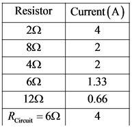
Now, current through circuit

Substitute 24 V for  and
and  for
for 

As 
Current through both of them is same and equal to current through circuit

In  , 8
, 8 and
and  are connected parallel and have same resistance, current in them will be equally divided.
Therefore,

In  ,
,  are in series, therefore, current though them is same and equal to 2A

In  ,
,  are connected parallel,
  will be divided amongst them according to their resistance. Since
  is half the value of 12
 , the current passing through it will be double.
Therefore,

(b)
The voltage drops across each resistor can be given by

Across  resistor

Across  resistor

Across  resistor

Across  resistor

As Across  resistor

The current through each resistor is given by
The voltage-drop across each resistor is given by

Add Answer to:
For the circuit shown in the figure find the current through each resistor. For the circuit...
A. For the circuit shown in the figure(Figure 1) find the current through each resistor. B....
 A. For the circuit shown in the figure(Figure 1) find the
current through each resistor.
B. For the circuit shown in the figure find the potential
difference across each resistor.
24 V 4 Ω
A. For the circuit shown in the figure(Figure 1) find the
current through each resistor.
B. For the circuit shown in the figure find the potential
difference across each resistor.
24 V 4 Ω
For the circuit shown in the figure, find the current through and the potential difference across each resistor.
 For the circuit shown in the figure, find the current through
and the potential difference across each resistor.What is the current through the 3 Ω resistor?What is the current through the 4 Ω resistor? What is the potential difference across the 3 Ω resistor.What is the potential difference across the 4 Ω resistor?What is the potential difference across the 48 Ω resistor?What is the current through the 48 Ω resistor?What is the potential difference
across the 16 Ω resistor?What is the...
For the circuit shown in the figure, find the current through
and the potential difference across each resistor.What is the current through the 3 Ω resistor?What is the current through the 4 Ω resistor? What is the potential difference across the 3 Ω resistor.What is the potential difference across the 4 Ω resistor?What is the potential difference across the 48 Ω resistor?What is the current through the 48 Ω resistor?What is the potential difference
across the 16 Ω resistor?What is the...
For each circuit shown in the figure, find the current through and potential difference across each...
 For each circuit shown in the figure, find the current through
and potential difference across each resistor
Thank you!
4Ω 6Ω 24 V 24 Ω 812 24 Ω
For each circuit shown in the figure, find the current through
and potential difference across each resistor
Thank you!
4Ω 6Ω 24 V 24 Ω 812 24 Ω
a) For the circuit shown in the figure find the currentthrough each resistor.b) For...
 a) For the circuit shown in the figure find the current
through each resistor.b) For the circuit shown in the figure find the potential
difference across each resistor.
a) For the circuit shown in the figure find the current
through each resistor.b) For the circuit shown in the figure find the potential
difference across each resistor.
For the circuit shown in the figure (Figure 1), find the current through and the potential...
 For the circuit shown in the figure (Figure 1), find the current through and the potential difference across each resistor. For the steps and strategies involved in solving a similar problem, you may view a Video Tutor Solution.
1 Circuit Analysis For the circuit shown in Figure 1, find the current through and the...
 1 Circuit Analysis For the circuit shown in Figure 1, find the current through and the potential difference across each resistor. Place your results in a table for ease of reading. Please follow the context-Rich solution format. For sense-making, please try to reason why the amount of current through each resistor makes sense. Figure 1: 3 Ω 16 Ω 4822 12 V 412
(A) For the circuit shown in the figure(Figure 1) find thecurrent through each resistor.Express...
 (A) For the circuit shown in the figure(Figure 1) find the
current through each resistor.Express your answers using two significant figures. Enter your
answers numerically separated by commas.(B)For the circuit shown in the figure find the potential
difference across each resistor.Express your answers using two significant figures. Enter your
answers numerically separated by commas.
(A) For the circuit shown in the figure(Figure 1) find the
current through each resistor.Express your answers using two significant figures. Enter your
answers numerically separated by commas.(B)For the circuit shown in the figure find the potential
difference across each resistor.Express your answers using two significant figures. Enter your
answers numerically separated by commas.
For the circuit shown in the figure below, find the current through and the potential difference...
 For the circuit shown in the figure below, find the current through and the potential difference across each resistor. Place your results in the table for ease of reading. (Assume R1 = 27 ohm, R2 = 2 ohm, and V = 2 V.)
Chapter 27, Problem 21. Find the current through each resistor in the circuit shown in Figure...
 Chapter 27, Problem 21. Find the current through each resistor in the circuit shown in Figure 27.P10 Find the potential difference between points A and H. Which point is at the higher potential? Use these values: epsilon_i - 12.0 V, epsilon_2 = 8.00 V. R_1 = 4.00 k Ohm, R_2 = 4.00 k Ohm, R_3 = 2.00 k Ohm
Find current and potential difference across each resistor
 a.) Find the current through resistor a) in the figure.b.) Find the potential difference across resistor a) in the figure.c.) Find the current through resistor b) in the figure.d.) Find the potential difference across resistor b) in the figure.e.) Find the current through resistor c) in the figure.f.) Find the potential difference across resistor c) in the figure.g.) Find the current through resistor d) in the figure.h.) Find the potential difference across resistor d) in the figure.I can tell that...
 A. For the circuit shown in the figure(Figure 1) find the
current through each resistor.
B. For the circuit shown in the figure find the potential
difference across each resistor.
24 V 4 Ω
A. For the circuit shown in the figure(Figure 1) find the
current through each resistor.
B. For the circuit shown in the figure find the potential
difference across each resistor.
24 V 4 Ω
 For the circuit shown in the figure, find the current through
and the potential difference across each resistor.What is the current through the 3 Ω resistor?What is the current through the 4 Ω resistor? What is the potential difference across the 3 Ω resistor.What is the potential difference across the 4 Ω resistor?What is the potential difference across the 48 Ω resistor?What is the current through the 48 Ω resistor?What is the potential difference
across the 16 Ω resistor?What is the...
For the circuit shown in the figure, find the current through
and the potential difference across each resistor.What is the current through the 3 Ω resistor?What is the current through the 4 Ω resistor? What is the potential difference across the 3 Ω resistor.What is the potential difference across the 4 Ω resistor?What is the potential difference across the 48 Ω resistor?What is the current through the 48 Ω resistor?What is the potential difference
across the 16 Ω resistor?What is the...
 For each circuit shown in the figure, find the current through
and potential difference across each resistor
Thank you!
4Ω 6Ω 24 V 24 Ω 812 24 Ω
For each circuit shown in the figure, find the current through
and potential difference across each resistor
Thank you!
4Ω 6Ω 24 V 24 Ω 812 24 Ω
 a) For the circuit shown in the figure find the current
through each resistor.b) For the circuit shown in the figure find the potential
difference across each resistor.
a) For the circuit shown in the figure find the current
through each resistor.b) For the circuit shown in the figure find the potential
difference across each resistor.
 For the circuit shown in the figure (Figure 1), find the current through and the potential difference across each resistor. For the steps and strategies involved in solving a similar problem, you may view a Video Tutor Solution.
 1 Circuit Analysis For the circuit shown in Figure 1, find the current through and the potential difference across each resistor. Place your results in a table for ease of reading. Please follow the context-Rich solution format. For sense-making, please try to reason why the amount of current through each resistor makes sense. Figure 1: 3 Ω 16 Ω 4822 12 V 412
 (A) For the circuit shown in the figure(Figure 1) find the
current through each resistor.Express your answers using two significant figures. Enter your
answers numerically separated by commas.(B)For the circuit shown in the figure find the potential
difference across each resistor.Express your answers using two significant figures. Enter your
answers numerically separated by commas.
(A) For the circuit shown in the figure(Figure 1) find the
current through each resistor.Express your answers using two significant figures. Enter your
answers numerically separated by commas.(B)For the circuit shown in the figure find the potential
difference across each resistor.Express your answers using two significant figures. Enter your
answers numerically separated by commas.
 For the circuit shown in the figure below, find the current through and the potential difference across each resistor. Place your results in the table for ease of reading. (Assume R1 = 27 ohm, R2 = 2 ohm, and V = 2 V.)
 Chapter 27, Problem 21. Find the current through each resistor in the circuit shown in Figure 27.P10 Find the potential difference between points A and H. Which point is at the higher potential? Use these values: epsilon_i - 12.0 V, epsilon_2 = 8.00 V. R_1 = 4.00 k Ohm, R_2 = 4.00 k Ohm, R_3 = 2.00 k Ohm
Most questions answered within 3 hours.
-
A monopoly sells in two countries . The demand curves in the two
countries are p1...
asked 44 minutes ago -
A .15kg rubber ball is bounced off a wall. Before hitting the
wall, the ball moves...
asked 1 hour ago -
A manufacturing company preparing to build a new plant is
considering three potential locations for it....
asked 1 hour ago -
B. If compound Y has approximately the same values of solubility
in toluene as compound X,...
asked 2 hours ago -
Oscar Inc. has inventory in Japan valued at 39,051,000 Yen one
year ago. One year ago...
asked 2 hours ago -
If Canada suffered from "fundamental disequilibrium," and its
government choose not to devalue its currency, a...
asked 2 hours ago -
4. How many input & output Key Value Pairs are passed into,
and emitted out of...
asked 2 hours ago -
Why would your heart not function well if constructed of
skeletal muscle? What is the particular...
asked 2 hours ago -
Please respond to this essay question in full essay form for
Chemistry 1102 Organic and Biochemistry:...
asked 2 hours ago -
Determine the head loss and velocity of flow in a water supply main
of 15.0 cm...
asked 2 hours ago -
A marketing executive who knowingly authorizes a shoddy
defective product to be brought to market is...
asked 2 hours ago -
Write a psudocode:
1. Define a function called authorize that takes in 2 strings,
uName, and...
asked 2 hours ago