Learning Goal: To understand the behavior of the current andvoltage in a simple R-C circuit...
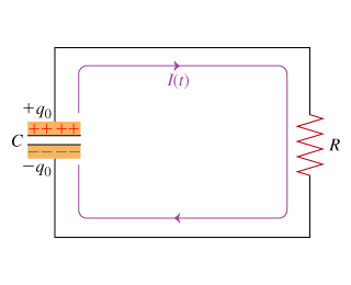
Learning Goal: To understand the behavior of the current and voltage in a simple R-C circuit A capacitor with capacitance C is initially charged with charge q0. At time t=0 a resistor with resistance R is connected across the capacitor. (Figure 1)
Part A
Use the Kirchhoff loop rule and Ohm's law to express the voltage across the capacitor V(t) in terms of the currentI(t) flowing through the circuit.
Express your answer in terms of I(t) andR.
| V(t) = |
Homework Answers

Add Answer to:
Learning Goal: To understand the behavior of the current andvoltage in a simple R-C circuit...
Learning Goal: To understand the dynamics ofaseries R-C circuit.Consider a series circuit containing a...
Learning Goal: To understand the dynamics of aseries R-C circuit.Consider a series circuit containing a resistor of resistance R anda capacitor of capacitance C connected to a source ofEMF ε with negligible internal resistance. The wiresare also assumed to have zero resistance. Initially, the switch isopen and the capacitor discharged.Let us try to understand the processes that take place afterthe switch is closed. The charge of the capacitor, the current inthe circuit, and, correspondingly, the voltages across the resistorand the...
Learning Goal: To understand the dynamics of a series R-C circuit. Consider a series circuit containing...
 Learning Goal: To understand the dynamics of a series R-C circuit. Consider a series circuit containing a resistor of resistance R and a capacitor of capacitance C connected to a source of EMF ε with negligible internal resistance. The wires are also assumed to have zero resistance. Initially, the switch is open and the capacitor discharged. (Figure 1)Let us try to understand the processes that take place after the switch is closed. The charge of the capacitor, the current in...
Part A Learning Goal To understand the dynamics of a series R-C circuit. Immediately after the...
 Part A Learning Goal To understand the dynamics of a series R-C circuit. Immediately after the switch is closed, what is the voltage across the capacitor? Consider a series circuit containing a resistor of resistance R and a capacitor of capacitance C connected to a source of EMF with negligible internal resistance. The wires are also assumed to have zero resistance. Initially, the switch is open and the capacitor discharged. (Figure 1) zero Let us try to understand the processes...
A capacitor with capacitance C is initially charged with charge q0. At time t = 0 a resistor with resistance R is connected across the capacitor. (Figure 1)
 To understand the behavior of the current and voltage in a simple R-C circuit. A capacitor with capacitance C is initially charged with charge q0. At time t = 0 a resistor with resistance R is connected across the capacitor. (Figure 1) Part CNow solve the differential equation V(t) = -CR dV(t)/dt for the initial conditions given in the problem introduction to find the voltage as a function of time for any time t.
Learning Goal: To understand the use of phasor diagrams in calculating the impedance and resonance conditions in a seri...
 Learning Goal: To understand the use of phasor diagrams in calculating the impedance and resonance conditions in a series L-R-C circuit. At resonance, XL = Xc. The voltage across the capacitor exactly cancels that across the i have the same amplitude. Thus, the inductor and capacitor effectively cancel out in the formu not come as a surprise that the resonant frequency equals the natural frequency of the oscilla In this problem, you will consider a series L-R-C circuit, containing a...
To understand the dynamics of a seriesR-C circuit.Consider a series circuitcontaining a resistor...
 To understand the dynamics of a series
R-C circuit.Consider a series circuit
containing a resistor of resistance R and a capacitor of capacitance Cconnected to a source of EMF E with negligible internal resistance. The wires
are also assumed to have zero resistance. Initially, the switch is
open and the capacitor discharged. (Figure 1)Let us try to understand the processes that take
place after the switch is closed. The charge of the capacitor, the
current in the circuit, and, correspondingly,...
To understand the dynamics of a series
R-C circuit.Consider a series circuit
containing a resistor of resistance R and a capacitor of capacitance Cconnected to a source of EMF E with negligible internal resistance. The wires
are also assumed to have zero resistance. Initially, the switch is
open and the capacitor discharged. (Figure 1)Let us try to understand the processes that take
place after the switch is closed. The charge of the capacitor, the
current in the circuit, and, correspondingly,...
Experiment 7 - The Resistor Capacitor Circuit Learning Objectives: Understand the short and long time behavior...
 Experiment 7 - The Resistor Capacitor Circuit Learning Objectives: Understand the short and long time behavior of circuits containing capacitors. Understand the and the mathematical relationshin between the current through the circuit as a function time, resistance, capacitance, and potential difference 1. Understanding the models for the behavior of a capacitor in a circuit A capacitor is a device that stores energy in a circuit as potential energy in an electric field. In the simple circuit drawn on the night,...
Decay of Current in an L-R Circuit
 Learning Goal: To understand the mathematics of current decay in an L-R circuitA DC voltage source is connected to a resistor of resistance R and an inductor with inductance L, forming the circuit shown in the figure. For a long time before t=0, the switch has been in the position shown, so that a current I0 has been built up in the circuit by the voltage source. At t=0 the switch is thrown to remove the voltage source from the circuit. This...
Learning Goal: To analyze an RC circuit to determine the initial voltage across a capacitor, the...
 Learning Goal: To analyze an RC circuit to determine the initial voltage across a capacitor, the time constant, and the expression for the natural response of the capacitor voltage, and then to find other circuit quantities such as current,voltage, power, or energy. The natural response of an RC circuit is the response of the capacitor voltage to the sudden removal of a DC source. When this occurs, the capacitor releases its stored energy Figure < 10121〉 t 0 V. Figure...
GOAL Calculate a time constant and relate it to current in an RL circuit. PROBLEM A...
 GOAL Calculate a time constant and relate it to
current in an RL circuit.
PROBLEM A 12.6-V battery is in a circuit with a
30.0-mH inductor and a 0.150-? resistor. The switch is closed at
t = 0. (a) Find the time constant of the
circuit. (b) Find the current after one time
constant has elapsed. (c) Find the voltage drops
across the resistor when t = 0 and t = one time
constant. (d) What's the rate of change...
GOAL Calculate a time constant and relate it to
current in an RL circuit.
PROBLEM A 12.6-V battery is in a circuit with a
30.0-mH inductor and a 0.150-? resistor. The switch is closed at
t = 0. (a) Find the time constant of the
circuit. (b) Find the current after one time
constant has elapsed. (c) Find the voltage drops
across the resistor when t = 0 and t = one time
constant. (d) What's the rate of change...
 Part A Learning Goal To understand the dynamics of a series R-C circuit. Immediately after the switch is closed, what is the voltage across the capacitor? Consider a series circuit containing a resistor of resistance R and a capacitor of capacitance C connected to a source of EMF with negligible internal resistance. The wires are also assumed to have zero resistance. Initially, the switch is open and the capacitor discharged. (Figure 1) zero Let us try to understand the processes...
 Learning Goal: To understand the use of phasor diagrams in calculating the impedance and resonance conditions in a series L-R-C circuit. At resonance, XL = Xc. The voltage across the capacitor exactly cancels that across the i have the same amplitude. Thus, the inductor and capacitor effectively cancel out in the formu not come as a surprise that the resonant frequency equals the natural frequency of the oscilla In this problem, you will consider a series L-R-C circuit, containing a...
 To understand the dynamics of a series
R-C circuit.Consider a series circuit
containing a resistor of resistance R and a capacitor of capacitance Cconnected to a source of EMF E with negligible internal resistance. The wires
are also assumed to have zero resistance. Initially, the switch is
open and the capacitor discharged. (Figure 1)Let us try to understand the processes that take
place after the switch is closed. The charge of the capacitor, the
current in the circuit, and, correspondingly,...
To understand the dynamics of a series
R-C circuit.Consider a series circuit
containing a resistor of resistance R and a capacitor of capacitance Cconnected to a source of EMF E with negligible internal resistance. The wires
are also assumed to have zero resistance. Initially, the switch is
open and the capacitor discharged. (Figure 1)Let us try to understand the processes that take
place after the switch is closed. The charge of the capacitor, the
current in the circuit, and, correspondingly,...
 Experiment 7 - The Resistor Capacitor Circuit Learning Objectives: Understand the short and long time behavior of circuits containing capacitors. Understand the and the mathematical relationshin between the current through the circuit as a function time, resistance, capacitance, and potential difference 1. Understanding the models for the behavior of a capacitor in a circuit A capacitor is a device that stores energy in a circuit as potential energy in an electric field. In the simple circuit drawn on the night,...
 Learning Goal: To analyze an RC circuit to determine the initial voltage across a capacitor, the time constant, and the expression for the natural response of the capacitor voltage, and then to find other circuit quantities such as current,voltage, power, or energy. The natural response of an RC circuit is the response of the capacitor voltage to the sudden removal of a DC source. When this occurs, the capacitor releases its stored energy Figure < 10121〉 t 0 V. Figure...
 GOAL Calculate a time constant and relate it to
current in an RL circuit.
PROBLEM A 12.6-V battery is in a circuit with a
30.0-mH inductor and a 0.150-? resistor. The switch is closed at
t = 0. (a) Find the time constant of the
circuit. (b) Find the current after one time
constant has elapsed. (c) Find the voltage drops
across the resistor when t = 0 and t = one time
constant. (d) What's the rate of change...
GOAL Calculate a time constant and relate it to
current in an RL circuit.
PROBLEM A 12.6-V battery is in a circuit with a
30.0-mH inductor and a 0.150-? resistor. The switch is closed at
t = 0. (a) Find the time constant of the
circuit. (b) Find the current after one time
constant has elapsed. (c) Find the voltage drops
across the resistor when t = 0 and t = one time
constant. (d) What's the rate of change...
Most questions answered within 3 hours.
-
A monopoly sells in two countries . The demand curves in the two
countries are p1...
asked 22 minutes ago -
A .15kg rubber ball is bounced off a wall. Before hitting the
wall, the ball moves...
asked 1 hour ago -
A manufacturing company preparing to build a new plant is
considering three potential locations for it....
asked 1 hour ago -
B. If compound Y has approximately the same values of solubility
in toluene as compound X,...
asked 1 hour ago -
Oscar Inc. has inventory in Japan valued at 39,051,000 Yen one
year ago. One year ago...
asked 1 hour ago -
If Canada suffered from "fundamental disequilibrium," and its
government choose not to devalue its currency, a...
asked 2 hours ago -
4. How many input & output Key Value Pairs are passed into,
and emitted out of...
asked 1 hour ago -
Why would your heart not function well if constructed of
skeletal muscle? What is the particular...
asked 2 hours ago -
Please respond to this essay question in full essay form for
Chemistry 1102 Organic and Biochemistry:...
asked 2 hours ago -
Determine the head loss and velocity of flow in a water supply main
of 15.0 cm...
asked 2 hours ago -
A marketing executive who knowingly authorizes a shoddy
defective product to be brought to market is...
asked 2 hours ago -
Write a psudocode:
1. Define a function called authorize that takes in 2 strings,
uName, and...
asked 2 hours ago