
Homework Answers

Add Answer to:
Figure 5 shows a piece of fitness equipment installed in a park. The horizontal part of...
P=10 kN A cantilever beam is subiected to a concentrated force P, a uniformly distributed load...
 P=10 kN A cantilever beam is subiected to a concentrated force P, a uniformly distributed load w and a moment MI shown in the figure. Neglect the weight of the beam. (a) Draw the free body diagram for the beam showing all the 2 m reactions, replacing the support M.-2 kNm by the reaction forces/moments. (b) Use the equations of equilibrium to find the reaction forces/moments at R (c) Give the expression for the shear force, V- V(x), and the...
x7=12KN , x8=19kN/m, x4=4m, x5=39m, x6=5m, Q2. In the 3-span beam shown in the Figure 2, the...
 x7=12KN , x8=19kN/m, x4=4m, x5=39m, x6=5m,
Q2. In the 3-span beam shown in the Figure 2, the support at C settles by 15 mm. Using the method of moment distribution method, a) Calculate joint moments (10 marks); b) Draw the bending moment diagram (10 marks); c) Calculate the supports' vertical reactions (10 marks); and d) Draw the shear force diagram (5 marks). Hint: For the calculation of Fixed End Moments, you can use the principle of superposition to add the settlement-related...
x7=12KN , x8=19kN/m, x4=4m, x5=39m, x6=5m,
Q2. In the 3-span beam shown in the Figure 2, the support at C settles by 15 mm. Using the method of moment distribution method, a) Calculate joint moments (10 marks); b) Draw the bending moment diagram (10 marks); c) Calculate the supports' vertical reactions (10 marks); and d) Draw the shear force diagram (5 marks). Hint: For the calculation of Fixed End Moments, you can use the principle of superposition to add the settlement-related...
Figure 1 shows a simply supported beam with load P applied at point C and D....
 Figure 1 shows a simply supported beam with load P applied at point C and D. If P = 40 kN, L= 3 m and a = 1 m, (a) draw the free-body diagram of the beam; (b) determine the support reaction forces at A and B; (c) determine the shear force and moment in AC, CD and DB sections; (d) draw the shear and moment diagrams of the beam. P P A B D X a a L
Consider the beam shown in the figure: (12 marks] a- Use the section method to draw...
 Consider the beam shown in the figure: (12 marks] a- Use the section method to draw the shear force and bending moment diagrams for the beam shown. Label all significant points on each diagram. And identify the maximum moments along with their respective locations. [10 marks] b- Determine V and M in the beam at a point located 1.50 m to the right of B. [1 mark] C- Determine V and M in the beam at a point located 1.25...
Problem 3 (19 points): A simply supported beam ABCD carries a uniformly distributed load, w, and...
 Problem 3 (19 points): A simply supported beam ABCD carries a uniformly distributed load, w, and a concentrated load, F, as shown in the figure. All the dimensions are given in the figure, and the weight of the beam is neglected a) Draw the free body diagram for the beam, showing all the applied and reaction forces. Find the reaction forces F=14 kN .6m b) Give the expression for the shear force, V- V(x), and the bending moment M M(x),...
The figure shows a mechanical device in which force (s) are applied parallel to and away...
 The figure shows a mechanical device in which force
(s) are applied parallel to and away from the axis of the main,
beam-like part. The device is supported by bearings at the
locations marked with an X, which can provide reaction forces in
any direction perpendicular to the axis of the beam. One of the
bearings has the capability of resisting horizontally directed
forces
1. Break the compound beam into parts consisting of each of the
straight components.
2. Show...
The figure shows a mechanical device in which force
(s) are applied parallel to and away from the axis of the main,
beam-like part. The device is supported by bearings at the
locations marked with an X, which can provide reaction forces in
any direction perpendicular to the axis of the beam. One of the
bearings has the capability of resisting horizontally directed
forces
1. Break the compound beam into parts consisting of each of the
straight components.
2. Show...
Problems for Figures P11-77 to P11-84 Each Figure shows a mechanical device in which one or...
 Problems for Figures P11-77 to P11-84 Each Figure shows a mechanical device in which one or more forces are applied parallel to and away from the axis of the main, beam-like part. The devices are supported by bearings at the locations marked with an X, which can provide reaction forces in any direction per pendicular to the axis of the beam. One of the bearings has the capa bility of resisting horizontally directed forces. For each figure the objectives are...
A loaded beam with a pin support at B and a rller support at C is shown in Figure 1. The applied loads on the bea...
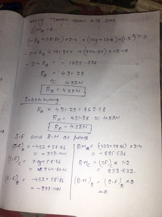
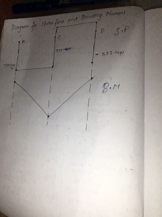
 A loaded beam with a pin support at B and a rller support at C is shown in Figure 1. The applied loads on the beam are: an anti-clockwise point moment at A, a variably distributed load between B and C, and a clockwise point moment at D g kN/m f kNm h kN m A C 4 m 2 m 2 m Figure 1 The magnitude of the anti-clockwise point moment f in units of kN'm can be found...
Question 3 128 Marks 2 rectangular beam shown in the figure is subjected to a fluctuating axial f...
 please draw and solve show every thing details “”
Question 3 128 Marks 2 rectangular beam shown in the figure is subjected to a fluctuating axial force. It fluctuates between 5 kN and 15 kN keeping its direction. The beam is to be machined to the dimensions shown in the figure with a transvers hole of diameter d-14 mm/ Material of the beam is AISI 1040 CD steel (S-590 stress concentration factor as 2.2. K Pa, Sy 490 MPa). Take...
please draw and solve show every thing details “”
Question 3 128 Marks 2 rectangular beam shown in the figure is subjected to a fluctuating axial force. It fluctuates between 5 kN and 15 kN keeping its direction. The beam is to be machined to the dimensions shown in the figure with a transvers hole of diameter d-14 mm/ Material of the beam is AISI 1040 CD steel (S-590 stress concentration factor as 2.2. K Pa, Sy 490 MPa). Take...
QUESTION 1 [25 marks A frame loaded with a uniformly distributed load at Member AB and...
 QUESTION 1 [25 marks A frame loaded with a uniformly distributed load at Member AB and point load at Member BC and joint B. It has pinned supports A and C, while joint B is fixed connected, as can be seen in Figure 1. Take E-200 GPa. a) Using the slope-deflection method, calculate the moments and illustrate the bending moment diagram. [15 marks) b) Then calculate the shear forces and sketch the shear force diagram. [10 marks) 22 KN 10...
 P=10 kN A cantilever beam is subiected to a concentrated force P, a uniformly distributed load w and a moment MI shown in the figure. Neglect the weight of the beam. (a) Draw the free body diagram for the beam showing all the 2 m reactions, replacing the support M.-2 kNm by the reaction forces/moments. (b) Use the equations of equilibrium to find the reaction forces/moments at R (c) Give the expression for the shear force, V- V(x), and the...
 x7=12KN , x8=19kN/m, x4=4m, x5=39m, x6=5m,
Q2. In the 3-span beam shown in the Figure 2, the support at C settles by 15 mm. Using the method of moment distribution method, a) Calculate joint moments (10 marks); b) Draw the bending moment diagram (10 marks); c) Calculate the supports' vertical reactions (10 marks); and d) Draw the shear force diagram (5 marks). Hint: For the calculation of Fixed End Moments, you can use the principle of superposition to add the settlement-related...
x7=12KN , x8=19kN/m, x4=4m, x5=39m, x6=5m,
Q2. In the 3-span beam shown in the Figure 2, the support at C settles by 15 mm. Using the method of moment distribution method, a) Calculate joint moments (10 marks); b) Draw the bending moment diagram (10 marks); c) Calculate the supports' vertical reactions (10 marks); and d) Draw the shear force diagram (5 marks). Hint: For the calculation of Fixed End Moments, you can use the principle of superposition to add the settlement-related...
 Figure 1 shows a simply supported beam with load P applied at point C and D. If P = 40 kN, L= 3 m and a = 1 m, (a) draw the free-body diagram of the beam; (b) determine the support reaction forces at A and B; (c) determine the shear force and moment in AC, CD and DB sections; (d) draw the shear and moment diagrams of the beam. P P A B D X a a L
 Consider the beam shown in the figure: (12 marks] a- Use the section method to draw the shear force and bending moment diagrams for the beam shown. Label all significant points on each diagram. And identify the maximum moments along with their respective locations. [10 marks] b- Determine V and M in the beam at a point located 1.50 m to the right of B. [1 mark] C- Determine V and M in the beam at a point located 1.25...
 Problem 3 (19 points): A simply supported beam ABCD carries a uniformly distributed load, w, and a concentrated load, F, as shown in the figure. All the dimensions are given in the figure, and the weight of the beam is neglected a) Draw the free body diagram for the beam, showing all the applied and reaction forces. Find the reaction forces F=14 kN .6m b) Give the expression for the shear force, V- V(x), and the bending moment M M(x),...
 The figure shows a mechanical device in which force
(s) are applied parallel to and away from the axis of the main,
beam-like part. The device is supported by bearings at the
locations marked with an X, which can provide reaction forces in
any direction perpendicular to the axis of the beam. One of the
bearings has the capability of resisting horizontally directed
forces
1. Break the compound beam into parts consisting of each of the
straight components.
2. Show...
The figure shows a mechanical device in which force
(s) are applied parallel to and away from the axis of the main,
beam-like part. The device is supported by bearings at the
locations marked with an X, which can provide reaction forces in
any direction perpendicular to the axis of the beam. One of the
bearings has the capability of resisting horizontally directed
forces
1. Break the compound beam into parts consisting of each of the
straight components.
2. Show...
 Problems for Figures P11-77 to P11-84 Each Figure shows a mechanical device in which one or more forces are applied parallel to and away from the axis of the main, beam-like part. The devices are supported by bearings at the locations marked with an X, which can provide reaction forces in any direction per pendicular to the axis of the beam. One of the bearings has the capa bility of resisting horizontally directed forces. For each figure the objectives are...
 A loaded beam with a pin support at B and a rller support at C is shown in Figure 1. The applied loads on the beam are: an anti-clockwise point moment at A, a variably distributed load between B and C, and a clockwise point moment at D g kN/m f kNm h kN m A C 4 m 2 m 2 m Figure 1 The magnitude of the anti-clockwise point moment f in units of kN'm can be found...
 please draw and solve show every thing details “”
Question 3 128 Marks 2 rectangular beam shown in the figure is subjected to a fluctuating axial force. It fluctuates between 5 kN and 15 kN keeping its direction. The beam is to be machined to the dimensions shown in the figure with a transvers hole of diameter d-14 mm/ Material of the beam is AISI 1040 CD steel (S-590 stress concentration factor as 2.2. K Pa, Sy 490 MPa). Take...
please draw and solve show every thing details “”
Question 3 128 Marks 2 rectangular beam shown in the figure is subjected to a fluctuating axial force. It fluctuates between 5 kN and 15 kN keeping its direction. The beam is to be machined to the dimensions shown in the figure with a transvers hole of diameter d-14 mm/ Material of the beam is AISI 1040 CD steel (S-590 stress concentration factor as 2.2. K Pa, Sy 490 MPa). Take...
 QUESTION 1 [25 marks A frame loaded with a uniformly distributed load at Member AB and point load at Member BC and joint B. It has pinned supports A and C, while joint B is fixed connected, as can be seen in Figure 1. Take E-200 GPa. a) Using the slope-deflection method, calculate the moments and illustrate the bending moment diagram. [15 marks) b) Then calculate the shear forces and sketch the shear force diagram. [10 marks) 22 KN 10...
Most questions answered within 3 hours.
-
Computer Programming II CS141(Java)
Mention the appropriate relationship between following
classes:
HOD–StaffMember
Car–Ferrari
Student-Address
BankAccount–FixedAccount
House-Building...
asked 2 hours ago -
Assume one of your finals has 50 questions on it, and
lucky for you, it's all...
asked 4 hours ago -
Rice Products in Bangladesh
Business behavior is derived in large part from the basic cultural
environment...
asked 5 hours ago -
The following base sequence is found for a mRNA fragment from
wild-type E. coli: 5'- UAUCAGUAGAUAAUGUAACC-3'...
asked 5 hours ago -
For this exercise, round all regression parameters to three
decimal places.
One of the two tables...
asked 6 hours ago -
What is the 5% level of significance for mean = 3.60, standard
deviation = 0.94, and...
asked 6 hours ago -
Prior to beginning work on this discussion, please read the
article by Hayley Peterson, 15 Companies...
asked 6 hours ago -
Which pair of aqueous solutions, when mixed, will form a
precipitate?
A) NaNO3 and AgC2H3O2
B)...
asked 6 hours ago -
1-Write an algorithm to get two numbers from the user (as
inputs) and calculate the sum...
asked 10 hours ago -
Define white-collar crime. What is the difference between
offender and offense-based definitions of white-collar crime? What...
asked 10 hours ago -
Consider a reaction which is 1st order with respect to A and 1st
order with respect...
asked 11 hours ago -
c++
The length of the hypotenuse of a right-angled triangle is the
square root of the...
asked 11 hours ago