
Homework Answers

Add Answer to:
The beam shown is under the w = 20 kife Q- Draw the shear diagram and...
The member shown above has a W - shape cross séction. FIND a) draw the shear, moment and normal force diagram
 The member shown above has a W - shape cross séction. FINDa) draw the shear, moment and normal force diagramb) determine the absolute maximum bending stress in the beam and
draw the stress distribution over the cross section at this
location.c) draw the transverse shear stress distribution over the cross
section just to the right of point B.d) determine the state of stress that the loading produces at
point E and point F.e) Draw mohr's circle for state of stress at...
The member shown above has a W - shape cross séction. FINDa) draw the shear, moment and normal force diagramb) determine the absolute maximum bending stress in the beam and
draw the stress distribution over the cross section at this
location.c) draw the transverse shear stress distribution over the cross
section just to the right of point B.d) determine the state of stress that the loading produces at
point E and point F.e) Draw mohr's circle for state of stress at...
For the beam shown in the figure below a. Draw the shear and moment diagrams for this beam
 For the beam shown in the figure below a. Draw the shear and moment diagrams for this beam b. Calculate the maximum bending stress, maximum axial stress, and maximum shear stress acting on the beam cross section c. Sketch the distributions of shear stresses and bending stresses acting on the beam cross section at the locations where these stresses are maximum.
(a) Sketch the shear force and bending moment diagram for the beam shown. Indicate the values and locations of maximum shear and moment.
 (a) Sketch the shear force and bending moment diagram for the beam shown. Indicate the values and locations of maximum shear and moment. (b) With the beam cross section shown, determine the maximum tensile stress, maximum compressive stress, and maximum transverse shear stress in the beam.
Problem 1: Draw the shear force and bending moment diagram for the beam shown below. (10)...
 Problem 1: Draw the shear force and bending moment diagram for the beam shown below. (10) Estimate the maximum bending stress located at section C (shown below). (10) Clearly identify the location on the cross section where the maximum bending stress is located. Is it tensile or compressive? Explain your answer.
Question 2: A simply supported beam under loading as shown in Figure 1: 1. Draw the influence lines of the bending moment and shear force at point C (L/4) Using the influence lines to determine t...
 Question 2: A simply supported beam under loading as shown in Figure 1: 1. Draw the influence lines of the bending moment and shear force at point C (L/4) Using the influence lines to determine the bending moment and shear force at section C due to the loading as shown in the figure. 2. 3. There is a distributed live load (w#2.5kN/m) which can vary the location along the beam. Determine the location of the live loads which create the...
Blem 2. (70 points) 1. For the beam shown in Figure (a): a) b) draw the shear force and bending m...
 blem 2. (70 points) 1. For the beam shown in Figure (a): a) b) draw the shear force and bending moment diagrams. (30 points) Select the most economical W shape for the beam with an allowable bending stress of 30 ksi. (10 points) determine the maximum tensile and compressive bending stresses at any location along the beam if the section shown in Figure (b) is used instead of the W shape section selectedin Part b. Would the beam be safe...
The 25 foot beam is loaded as shown below. a. (10 points) Draw the shear and...
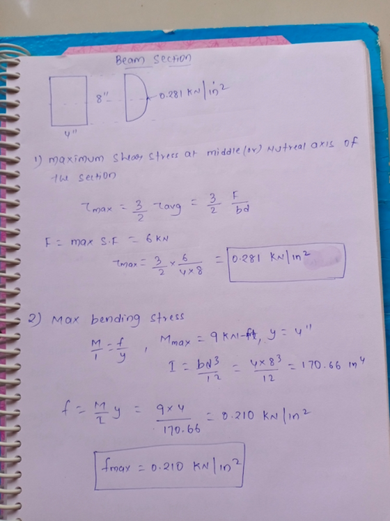
 The 25 foot beam is loaded as shown below. a. (10 points) Draw the shear and bending moment diagrams for this beam. b. (15 points) What is the value of the maximum normal tensile and compressive stress in the beam? C. (10 points) What is the value of the maximum shear stress in the beam? 2 kips 3 kips w = 1 kip/ft VE VE 10 ft 5 ft 5 ft 5 ft 20 Beam Cross-Section
For the beam and loading shown, (a) draw thr shear and bending-moment diagram, (b) determine the...
 For the beam and loading shown, (a) draw thr shear and
bending-moment diagram, (b) determine the maximum absolute value of
the bending moment.
Fig. P7.31
For the beam and loading shown, (a) draw thr shear and
bending-moment diagram, (b) determine the maximum absolute value of
the bending moment.
Fig. P7.31
(a) Draw the load (FBD), shear, and bending moment diagrams for the beam shown. (b) Write...
 (a) Draw the load (FBD), shear, and bending moment diagrams for the beam shown. (b) Write the equations for Vix) and M(x), taking the origin at the left end of the beam. (c) Taking the cross section to be C 380 x 74 (page 812 of Text), determine the maximum bending stress at the section where the moment (absolute value) is maximum. (d) Determine the maximum shear stress at the section 2 m from the left end. 40 kN/m15 kN...
For the beam shown in the given figure:
 For the beam shown in the given figure: (a) Express the internal shear (V) and moment (M) in the beam as a function of x. (b) Draw the shear force diagram (SFD) and bending moment diagram (BMD). (c) If the area moment of inertia (I) of the beam's cross section about the neutral axis is 301.3 (10-6)m4, determine the absolute maximum bending stress (σmax) in the beam.
 Problem 1: Draw the shear force and bending moment diagram for the beam shown below. (10) Estimate the maximum bending stress located at section C (shown below). (10) Clearly identify the location on the cross section where the maximum bending stress is located. Is it tensile or compressive? Explain your answer.
 Question 2: A simply supported beam under loading as shown in Figure 1: 1. Draw the influence lines of the bending moment and shear force at point C (L/4) Using the influence lines to determine the bending moment and shear force at section C due to the loading as shown in the figure. 2. 3. There is a distributed live load (w#2.5kN/m) which can vary the location along the beam. Determine the location of the live loads which create the...
 blem 2. (70 points) 1. For the beam shown in Figure (a): a) b) draw the shear force and bending moment diagrams. (30 points) Select the most economical W shape for the beam with an allowable bending stress of 30 ksi. (10 points) determine the maximum tensile and compressive bending stresses at any location along the beam if the section shown in Figure (b) is used instead of the W shape section selectedin Part b. Would the beam be safe...
 The 25 foot beam is loaded as shown below. a. (10 points) Draw the shear and bending moment diagrams for this beam. b. (15 points) What is the value of the maximum normal tensile and compressive stress in the beam? C. (10 points) What is the value of the maximum shear stress in the beam? 2 kips 3 kips w = 1 kip/ft VE VE 10 ft 5 ft 5 ft 5 ft 20 Beam Cross-Section
 For the beam and loading shown, (a) draw thr shear and
bending-moment diagram, (b) determine the maximum absolute value of
the bending moment.
Fig. P7.31
For the beam and loading shown, (a) draw thr shear and
bending-moment diagram, (b) determine the maximum absolute value of
the bending moment.
Fig. P7.31
 (a) Draw the load (FBD), shear, and bending moment diagrams for the beam shown. (b) Write the equations for Vix) and M(x), taking the origin at the left end of the beam. (c) Taking the cross section to be C 380 x 74 (page 812 of Text), determine the maximum bending stress at the section where the moment (absolute value) is maximum. (d) Determine the maximum shear stress at the section 2 m from the left end. 40 kN/m15 kN...
Most questions answered within 3 hours.
-
The extent to which assets are financed by borrowed funds and
other liabilities is indicated by:...
asked 50 minutes ago -
Explain in detail
Germany is the fifth largest economy
explain what goods and services Germany specializes...
asked 1 hour ago -
The density of platinum is 21.45 g/mL. If a cube of platinum
with a mass of...
asked 1 hour ago -
Accounts Receivable
Sales
A/R Posting
Extended Sales Invoice
Packing Slip
Compare invoice to packing slip 2...
asked 1 hour ago -
Michaella, age 23, is a full-time law student and is claimed by
her parents as a...
asked 1 hour ago -
Why are polymers not typically casted into products?
asked 1 hour ago -
When rolling a die 129 times, what is the probability of rolling
a 6 no more...
asked 1 hour ago -
4. A call option currently sells for $7.75. It has a strike
price of $85 and...
asked 1 hour ago -
1.
You need to prepare 10.0 liters of an acid aqueous solution with a
pH of...
asked 1 hour ago -
Along an aggregate supply curve, if the level of output is less
than the natural level...
asked 1 hour ago -
By 2025, annual consumption in emerging markets will total $30
trillion and contribute more than ________...
asked 1 hour ago -
At what point does reformation cease to be a viable option for
those who are oppressed...
asked 1 hour ago