
Homework Answers

Add Answer to:
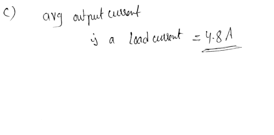
A chopper is supplied from a 240-V dc source. The load of the chopper con- sists...
1. A step-down chopper is connected to a 90VDC source and a 3Ω resistive load. The...
1. A step-down chopper is connected to a 90VDC source and a 3Ω resistive load. The chopper switching frequency is 5kHz with a 40% duty-cycle (D) Average free-wheeling diode current 2. A step-down chopper is connected to a 90VDC source and a 3Ω resistive load. The chopper switching frequency is 5kHz with a 40% duty-cycle (D) Size of inductance for a 10% peak-to-peak current ripple 3. VS = 90V EMF = 40V R = 2Ω L = 10mH switching frequency = 5kHz...
An ideal chopper operates at a frequency of 500 Hz. It is supplied from a dc...
 An ideal chopper operates at a frequency of 500 Hz. It is supplied from a dc source E = 60 V. The load consists of a 3-12. The inductance is 9-mH. Assume the diode is ideal and the battery is lossless. Assume periodic steady state and CCM. (2 points) Part a): Draw the circuit diagram. (3 points) Part b): Derive the expression for the load current, i.(t). (5 points) Part c): For tonitoff = 1/1, calculate and draw the current...
Both questions go together P6.8 A two-quadrant chopper, fed from a 400-V de source, supplies power to a dc motor whose armature resistance is 0.2 Ω. The armature current is to be maintained const...
 Both questions go together
P6.8 A two-quadrant chopper, fed from a 400-V de source, supplies power to a dc motor whose armature resistance is 0.2 Ω. The armature current is to be maintained constant at 250 A, independently of the motor speed that affects the armature EMF. Find the magnitude control ratio of the chopper and duty ratio of the modulating switch when the armature EMF is (a) 320 V (b) -320 v P6.9 For the chopper in Problem 6.8,...
Both questions go together
P6.8 A two-quadrant chopper, fed from a 400-V de source, supplies power to a dc motor whose armature resistance is 0.2 Ω. The armature current is to be maintained constant at 250 A, independently of the motor speed that affects the armature EMF. Find the magnitude control ratio of the chopper and duty ratio of the modulating switch when the armature EMF is (a) 320 V (b) -320 v P6.9 For the chopper in Problem 6.8,...
P8.8 A forward converter supplied from a 25-V de source operates with the switch- ing frequency...
 P8.8 A forward converter supplied from a 25-V de source operates with the switch- ing frequency of 50 kHz and duty ratio of 0.5. The turn ratio of the trans- former is 1:1, the output capacitance is 150 uF, and the load draws a current of 2.5 A. Select the minimum inductance for continuous conduction mode and determine the average value and ripple amplitude of the output voltage.
A PV array with terminal voltage around 48 V under standard conditions is connected to a step-up dc-dc converter to supply a load at 120 V, 5 A. The input inductance is 8 mH with an internal resistanc...
A PV array with terminal voltage around 48 V under standard conditions is connected to a step-up dc-dc converter to supply a load at 120 V, 5 A. The input inductance is 8 mH with an internal resistance of 0.2 ohms, and the switching frequency is 5 kHz. Assuming ideal circuit components, calculate the duty ratio (k) and average input current (I1). Evaluate the maximum peak-to-peak input current ripple for the converter. If this current is limited to 2% of...
Questions 1 to 3 relate to a three-phase SCR rectifier supplied from a 415 Vrms, 50 Hz ac source. For a 100 Ω resistive load, determine the peak, minimum and average load current for SCR firing angle...
 Questions 1 to 3 relate to a three-phase SCR rectifier supplied from a 415 Vrms, 50 Hz ac source. For a 100 Ω resistive load, determine the peak, minimum and average load current for SCR firing angles of: (a) a-0° (5.87 A, 5.08 A, 5.6 A) (b) α = 45° (5.67 A, 1.52 A, 3.96 A) (c) α-70° (4.5 A, 0 A, 2.0 A) How will your answers change if a very large inductance (zero resistance) is added in series...
Is N N Vo V's Vo Vs LOAD LOAD Figure 1 It has been shown in...
 Is N N Vo V's Vo Vs LOAD LOAD Figure 1 It has been shown in lectures that from the equality of power generation and power consumption, and as far as the average input/output voltages and currents are concerned, the buck and boost converters' operation in CCM (continuous current mode) are similar to the operation of the ideal AC transformers. So these converters may be considered as "ideal DC transformers". A buck converter operates with a duty cycle D 0.4,...
A three-phase full wave rectifier is supplied from a 420 rms line-to-line source. The load consists of a series connected 50 Ω resistor and 60 mH inductance. Determine the power delivered to the load...
A three-phase full wave rectifier is supplied from a 420 rms line-to-line source. The load consists of a series connected 50 Ω resistor and 60 mH inductance. Determine the power delivered to the load by assuming that all harmonics are negligible.
A single-phase full bridge thyristor rectifier is supplied from a 200vrm 50HZ AC source, and supplies...
 A single-phase full bridge thyristor rectifier is supplied from a 200vrm 50HZ AC source, and supplies a series R-L load comprising a 202 resistance and a 36.8mH inductance 2.a. Sketch the circuit diagram for this rectifier Q2. [4 marks] [Refer to lecture notes] 2.b. Determine the maximum possible average DC voltage that can be achieved across the load resistor [4 marks] [VDC (avg) = 180V] 2.c. Determine the SCR firing angle at which the rectified output curent will just be...
Buck Converter Question Q3. A Buck converter is used to produce a regulated 10V, 5A DC...
 Buck Converter Question
Q3. A Buck converter is used to produce a regulated 10V, 5A DC power supply from a variable DC source with an nominal input voltage of Vin = 20V±5V. The Buck converter switches at 250kHz, and operates entirely in the continuous conduction mode. The output filter capacitance is C1.0uF 3.a. Draw the circuit topology for the Buck converter. Ensure that your circuit includes the input DC source, the output load resistance, the switching devices (i.e. MOSFET and...
Buck Converter Question
Q3. A Buck converter is used to produce a regulated 10V, 5A DC power supply from a variable DC source with an nominal input voltage of Vin = 20V±5V. The Buck converter switches at 250kHz, and operates entirely in the continuous conduction mode. The output filter capacitance is C1.0uF 3.a. Draw the circuit topology for the Buck converter. Ensure that your circuit includes the input DC source, the output load resistance, the switching devices (i.e. MOSFET and...
 An ideal chopper operates at a frequency of 500 Hz. It is supplied from a dc source E = 60 V. The load consists of a 3-12. The inductance is 9-mH. Assume the diode is ideal and the battery is lossless. Assume periodic steady state and CCM. (2 points) Part a): Draw the circuit diagram. (3 points) Part b): Derive the expression for the load current, i.(t). (5 points) Part c): For tonitoff = 1/1, calculate and draw the current...
 Both questions go together
P6.8 A two-quadrant chopper, fed from a 400-V de source, supplies power to a dc motor whose armature resistance is 0.2 Ω. The armature current is to be maintained constant at 250 A, independently of the motor speed that affects the armature EMF. Find the magnitude control ratio of the chopper and duty ratio of the modulating switch when the armature EMF is (a) 320 V (b) -320 v P6.9 For the chopper in Problem 6.8,...
Both questions go together
P6.8 A two-quadrant chopper, fed from a 400-V de source, supplies power to a dc motor whose armature resistance is 0.2 Ω. The armature current is to be maintained constant at 250 A, independently of the motor speed that affects the armature EMF. Find the magnitude control ratio of the chopper and duty ratio of the modulating switch when the armature EMF is (a) 320 V (b) -320 v P6.9 For the chopper in Problem 6.8,...
 P8.8 A forward converter supplied from a 25-V de source operates with the switch- ing frequency of 50 kHz and duty ratio of 0.5. The turn ratio of the trans- former is 1:1, the output capacitance is 150 uF, and the load draws a current of 2.5 A. Select the minimum inductance for continuous conduction mode and determine the average value and ripple amplitude of the output voltage.
 Questions 1 to 3 relate to a three-phase SCR rectifier supplied from a 415 Vrms, 50 Hz ac source. For a 100 Ω resistive load, determine the peak, minimum and average load current for SCR firing angles of: (a) a-0° (5.87 A, 5.08 A, 5.6 A) (b) α = 45° (5.67 A, 1.52 A, 3.96 A) (c) α-70° (4.5 A, 0 A, 2.0 A) How will your answers change if a very large inductance (zero resistance) is added in series...
 Is N N Vo V's Vo Vs LOAD LOAD Figure 1 It has been shown in lectures that from the equality of power generation and power consumption, and as far as the average input/output voltages and currents are concerned, the buck and boost converters' operation in CCM (continuous current mode) are similar to the operation of the ideal AC transformers. So these converters may be considered as "ideal DC transformers". A buck converter operates with a duty cycle D 0.4,...
 A single-phase full bridge thyristor rectifier is supplied from a 200vrm 50HZ AC source, and supplies a series R-L load comprising a 202 resistance and a 36.8mH inductance 2.a. Sketch the circuit diagram for this rectifier Q2. [4 marks] [Refer to lecture notes] 2.b. Determine the maximum possible average DC voltage that can be achieved across the load resistor [4 marks] [VDC (avg) = 180V] 2.c. Determine the SCR firing angle at which the rectified output curent will just be...
 Buck Converter Question
Q3. A Buck converter is used to produce a regulated 10V, 5A DC power supply from a variable DC source with an nominal input voltage of Vin = 20V±5V. The Buck converter switches at 250kHz, and operates entirely in the continuous conduction mode. The output filter capacitance is C1.0uF 3.a. Draw the circuit topology for the Buck converter. Ensure that your circuit includes the input DC source, the output load resistance, the switching devices (i.e. MOSFET and...
Buck Converter Question
Q3. A Buck converter is used to produce a regulated 10V, 5A DC power supply from a variable DC source with an nominal input voltage of Vin = 20V±5V. The Buck converter switches at 250kHz, and operates entirely in the continuous conduction mode. The output filter capacitance is C1.0uF 3.a. Draw the circuit topology for the Buck converter. Ensure that your circuit includes the input DC source, the output load resistance, the switching devices (i.e. MOSFET and...
Most questions answered within 3 hours.
-
3) What are the typical social structures in a global city?
asked 1 hour ago -
Luther Corporation
Consolidated Balance Sheet
December 31, 2019 and 2018 (in $ millions)
Assets
2019
2018...
asked 1 hour ago -
(Expected rate of return and risk) Carter Inc. is evaluating a
security. Calculate the investment’s expected...
asked 4 hours ago -
What specific indicators can point to lack of progress for
African Americans in American society?
asked 5 hours ago -
1-The Electrons in a beam are moving at 2.7×10⁸ m/s in an
electric field of 15000...
asked 5 hours ago -
A gas tank is a vertical cylinder. It has a radius of 1m, a
height of...
asked 5 hours ago -
Accent Software faces the following conditions. All of these
support Accent’s use of a market-penetration pricing...
asked 6 hours ago -
A mathematically inclined friend emails you the following
instructions: "Meet me in the cafeteria the first...
asked 6 hours ago -
A monopoly sells in two countries . The demand curves in the two
countries are p1...
asked 7 hours ago -
A .15kg rubber ball is bounced off a wall. Before hitting the
wall, the ball moves...
asked 8 hours ago -
A manufacturing company preparing to build a new plant is
considering three potential locations for it....
asked 8 hours ago -
B. If compound Y has approximately the same values of solubility
in toluene as compound X,...
asked 9 hours ago