
Homework Answers

Add Answer to:
4. For the circuit shown, compute the voltage across the load terminals 0.10 j0.5Ω 1-600"A 1200...
Problem: (1) For the single phase AC circuit shown below, calculate voltage phasor across the loa...
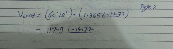
 Problem: (1) For the single phase AC circuit shown below, calculate voltage phasor across the load showing amplitude and phase angle for a (reference) source voltage of 220 V and 0 degree. Also, attach your MultiSIM simulation showing the voltage amplitude across the load. Compare simulated and calculated values. Load Bus of an Industrial Facility (equivalent of Electrical Motors and power factor correction Cap in parallel). R1 L1 Vload-? 1 3.0ohm 2 10mH 3 4.7mH 4 20ohm R2 +220V, 60...
Problem #4 In the voltage-divider circuit shown in Figure, the no-load value of y, is 4...
 Problem #4 In the voltage-divider circuit shown in Figure, the no-load value of y, is 4 V. When the load resistance R, is attached across the terminals a and b, v, drops to 3V. Find R 40.2 w 20 V 20v & R2 vo {RL
0 40 V The no-load voltage across R2 in the voltage-divider circuit shown is shown is...
 0 40 V The no-load voltage across R2 in the voltage-divider circuit shown is shown is vo.no_load 8 V The smallest load resistor that is ever connected to the divider is RL,smallest 3.6 k Ω (kilo Ohm) When the voltage divider is loaded by RLsmallest, VO is not to drop below 7.5 V A) Assume the power ratings of commercially available resistors are 1/16, 1/8, 1/4, 1, and 2 W What power rating would you specify? PR1,rating Watt PR2.rating =...
2- A circuit across the terminals of a sinusoidal voltage source, as shown in Figure 2....
 2- A circuit across the terminals of a sinusoidal voltage source, as shown in Figure 2. The steady-state expression for the source voltage is v;=50.cos(1000t+20). (40 points) 12 mH 100 MF 10 Figure 2 a) Construct the frequency-domain equivalent circuit. b) Calculate the steady-state current i by the phasor method.
3. (30% ) The voltage and current at the terminals of a load circuit are given...
 3. (30% ) The voltage and current at the terminals of a load circuit are given by: )=1202 sin(ar) V i ()=812 sin(ar-60)+6/2 sin(Bax -120) A (V) and (A). (a) Find (b) Find the real (average) power P delivered to the load. (c) The distortion factor of the current waveform. (e) Find the displacement power factor DPF for this circuit. (f) Find the power factor of the load. (g) Is the load linear? 3. (30% ) The voltage and current...
A resistor is placed in a circuit with an adjustable voltage source. The voltage across and...
 A resistor is placed in a circuit with an adjustable voltage source. The voltage across and the current through the resistor and the measurements are shown below. Estimate the resistance of the resistor (in 12). Voltage (V) 3000F 2400 1800 1200 600 Current (A) 10 2 4 6 8 X 12 Enter a number.
In the voltage-divider circuit shown in the figure, the no-load value of vo is 5 V...
 In the voltage-divider circuit shown in the figure, the no-load value of vo is 5 V When the load resistance RI is attached across the terminals a and b, vo drops to 3 V.(Figure 1) PartA Find RL Express your answer with the appropriate units RI-7.28 Submit Previous Answers Request Answer Incorrect, Try Again: One attempt remaining Provide Feedback igure 1 of 1 40Ω 20 V R2 vo
(3) a) For the circuit shown in Figure Q3, calculate the voltage across the load RL....
 (3) a) For the circuit shown in Figure Q3, calculate the voltage across the load RL. Assume the load is a welding system; calculate the voltage across the load considering the diodes are silicon (8 marks) b) Explain the role of the capacitor connected across the load. (2 marks) c) If the diodes D and D. are reversed, explain the consequences. (2 marks) Illustrate the waveform across the capacitor for Figure Q4 with respect to the secondary winding voltage (5...
The line-to-neutral voltage at the terminals of the balanced three-phase load in the circuit shown in...
 The line-to-neutral voltage at the terminals of the balanced three-phase load in the circuit shown in A I į 480, kVAI 1 08 pf Q Tap image to zoom is 1900 V.At this voltage, the load is absorbing 480 kVA at 0.8 pf lag Part A Use VAN as the reference and express Ina in polar form. Enter your answer using polar notation. Express argument in degrees. Submit Request Answer Part B Calculate the complex power associated with the ideal...
For the circuit shown, find the steady-state voltage across the inductor v (t), when us 1 (t) = 2...
 For the circuit shown, find the steady-state voltage across the inductor v (t), when us 1 (t) = 20 cos(1000t) V, vs2(t) = 30 cos(1000t-90') V, using: (a) The mesh-current method (b) The node-voltage method. (c) The Source transformation Method (d) The superposition Principle (e The Thevenin's equivalent at the terminals a-b. 200μF VL 15mH Vs2 10Ω
For the circuit shown, find the steady-state voltage across the inductor v (t), when us 1 (t) = 20 cos(1000t) V, vs2(t) =...
For the circuit shown, find the steady-state voltage across the inductor v (t), when us 1 (t) = 20 cos(1000t) V, vs2(t) = 30 cos(1000t-90') V, using: (a) The mesh-current method (b) The node-voltage method. (c) The Source transformation Method (d) The superposition Principle (e The Thevenin's equivalent at the terminals a-b. 200μF VL 15mH Vs2 10Ω
For the circuit shown, find the steady-state voltage across the inductor v (t), when us 1 (t) = 20 cos(1000t) V, vs2(t) =...
 Problem: (1) For the single phase AC circuit shown below, calculate voltage phasor across the load showing amplitude and phase angle for a (reference) source voltage of 220 V and 0 degree. Also, attach your MultiSIM simulation showing the voltage amplitude across the load. Compare simulated and calculated values. Load Bus of an Industrial Facility (equivalent of Electrical Motors and power factor correction Cap in parallel). R1 L1 Vload-? 1 3.0ohm 2 10mH 3 4.7mH 4 20ohm R2 +220V, 60...
 Problem #4 In the voltage-divider circuit shown in Figure, the no-load value of y, is 4 V. When the load resistance R, is attached across the terminals a and b, v, drops to 3V. Find R 40.2 w 20 V 20v & R2 vo {RL
 0 40 V The no-load voltage across R2 in the voltage-divider circuit shown is shown is vo.no_load 8 V The smallest load resistor that is ever connected to the divider is RL,smallest 3.6 k Ω (kilo Ohm) When the voltage divider is loaded by RLsmallest, VO is not to drop below 7.5 V A) Assume the power ratings of commercially available resistors are 1/16, 1/8, 1/4, 1, and 2 W What power rating would you specify? PR1,rating Watt PR2.rating =...
 2- A circuit across the terminals of a sinusoidal voltage source, as shown in Figure 2. The steady-state expression for the source voltage is v;=50.cos(1000t+20). (40 points) 12 mH 100 MF 10 Figure 2 a) Construct the frequency-domain equivalent circuit. b) Calculate the steady-state current i by the phasor method.
 3. (30% ) The voltage and current at the terminals of a load circuit are given by: )=1202 sin(ar) V i ()=812 sin(ar-60)+6/2 sin(Bax -120) A (V) and (A). (a) Find (b) Find the real (average) power P delivered to the load. (c) The distortion factor of the current waveform. (e) Find the displacement power factor DPF for this circuit. (f) Find the power factor of the load. (g) Is the load linear? 3. (30% ) The voltage and current...
 A resistor is placed in a circuit with an adjustable voltage source. The voltage across and the current through the resistor and the measurements are shown below. Estimate the resistance of the resistor (in 12). Voltage (V) 3000F 2400 1800 1200 600 Current (A) 10 2 4 6 8 X 12 Enter a number.
 In the voltage-divider circuit shown in the figure, the no-load value of vo is 5 V When the load resistance RI is attached across the terminals a and b, vo drops to 3 V.(Figure 1) PartA Find RL Express your answer with the appropriate units RI-7.28 Submit Previous Answers Request Answer Incorrect, Try Again: One attempt remaining Provide Feedback igure 1 of 1 40Ω 20 V R2 vo
 (3) a) For the circuit shown in Figure Q3, calculate the voltage across the load RL. Assume the load is a welding system; calculate the voltage across the load considering the diodes are silicon (8 marks) b) Explain the role of the capacitor connected across the load. (2 marks) c) If the diodes D and D. are reversed, explain the consequences. (2 marks) Illustrate the waveform across the capacitor for Figure Q4 with respect to the secondary winding voltage (5...
 The line-to-neutral voltage at the terminals of the balanced three-phase load in the circuit shown in A I į 480, kVAI 1 08 pf Q Tap image to zoom is 1900 V.At this voltage, the load is absorbing 480 kVA at 0.8 pf lag Part A Use VAN as the reference and express Ina in polar form. Enter your answer using polar notation. Express argument in degrees. Submit Request Answer Part B Calculate the complex power associated with the ideal...
 For the circuit shown, find the steady-state voltage across the inductor v (t), when us 1 (t) = 20 cos(1000t) V, vs2(t) = 30 cos(1000t-90') V, using: (a) The mesh-current method (b) The node-voltage method. (c) The Source transformation Method (d) The superposition Principle (e The Thevenin's equivalent at the terminals a-b. 200μF VL 15mH Vs2 10Ω
For the circuit shown, find the steady-state voltage across the inductor v (t), when us 1 (t) = 20 cos(1000t) V, vs2(t) =...
For the circuit shown, find the steady-state voltage across the inductor v (t), when us 1 (t) = 20 cos(1000t) V, vs2(t) = 30 cos(1000t-90') V, using: (a) The mesh-current method (b) The node-voltage method. (c) The Source transformation Method (d) The superposition Principle (e The Thevenin's equivalent at the terminals a-b. 200μF VL 15mH Vs2 10Ω
For the circuit shown, find the steady-state voltage across the inductor v (t), when us 1 (t) = 20 cos(1000t) V, vs2(t) =...
Most questions answered within 3 hours.
-
When disposable income is $1000, consumer spending is $950. The
value of the multiplier for this...
asked 3 minutes ago -
Calculate the pH of a buffer solution that is
0.116 M in
C2H5NH2
(ethylamine) and 0.403...
asked 3 minutes ago -
#include <iostream>
#include <vector>
using namespace std;
class Solution {
public:
vector<int> smallerNumbersThanCurrent(vector<int>&
nums) {
int...
asked 14 minutes ago -
1) What 8 guidelines should you follow to enable you to use
email efficiently and effectively...
asked 17 minutes ago -
What geographical obstacle seems to have taken the longest time
for modern humans to get across?...
asked 22 minutes ago -
When Maria Acosta bought a car 2 and a half
years ago, she borrowed $11,000 for...
asked 30 minutes ago -
package rectangle;
public class Rectangle {
private int height;
private int width;
public...
asked 32 minutes ago -
The Yankee's have a contract with their newly hired manager that
requires a lump sum payment...
asked 51 minutes ago -
A travelling salesman sells milkshake mixing machines and on
average sells 8.9 machines per month. He...
asked 56 minutes ago -
what's the danger in the fact that the market value of a stock
is based on...
asked 1 hour ago -
Describe how do you feel about the post below and
why?
Listening to the podcast reaffirmed...
asked 1 hour ago -
To start an avalanche on a mountain slope, an artillery shell is
fired with an initial...
asked 1 hour ago