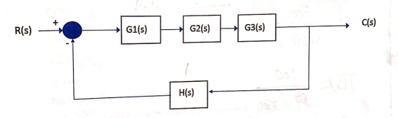
using following parameters as defined
G1(s)=1/(s+50)
G2(s)=K/s
G3(s)=1/(s+10)
H(s)=1
R(s) is the unit step function
a) find the closed loop transfer function as a function of K
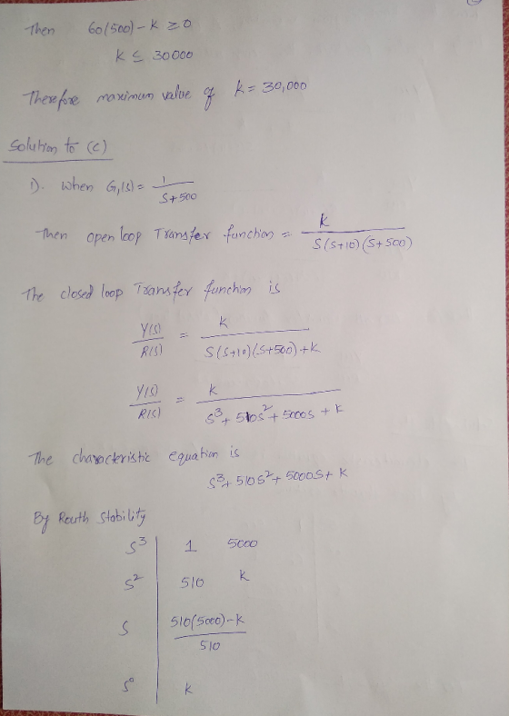
b) what is the maximum value of the K the system can tolerate?
c) is there an effect on the system if the pole in G1(s) is changed to :
1) G1(s)= 1/(s+500)
2) G1(s)=1/(s+11)
Homework Answers


Thankyou
Add Answer to:
using following parameters as defined
G1(s)=1/(s+50)
G2(s)=K/s
G3(s)=1/(s+10)
H(s)=1
R(s) is the unit step function
a)...
s G1 = G2 = S-8 G2 s2+1 G3= G4 = R(s) C(s) S G1 G3...
 s G1 = G2 = S-8 G2 s2+1 G3= G4 = R(s) C(s) S G1 G3 G4 H1 H2 si 28+3 H1 H2 a) Find the characteristic equation by subtracting the transfer function (C (s) / R (s)) of the system, whose block diagram is given above. b) Determine the stability of the given system with Routh-Hurwitz stability analysis method.
Find the closed-loop transfer function, T(s)-C(s)/R(s) for the following systems using block diagram reduction R(s)+ G1...
 Find the closed-loop transfer function, T(s)-C(s)/R(s) for the following systems using block diagram reduction R(s)+ G1 G2 G8 C(s) G2 G4 G7 G3 G1 G2 G3 G4. C(s) R(s)+ G5 G6 G7
3. There is a block diagram as shown in Fig. G1 G2 G3 Fig. 2 (a)...
 3. There is a block diagram as shown in Fig. G1 G2 G3 Fig. 2 (a) Convert the block diagram to a signal flow (b) Obtain its transfer function (G(s)-C(s)/R(s)) (c) As G -K.G3 G3 and its inputrt) is unit step, obtain the 50 condition of the P-controller(G1) for c(t) not to oscillate.
What is the transfer function of the following diagram? X(s) - G1(s) Y(s) block diagram G2(s)...
 What is the transfer function of the following diagram? X(s) - G1(s) Y(s) block diagram G2(s) G3(s) - Y(s)/X(s) = G1/(1+G1 +G2+G3) O Ys/X(s) = G1/(1 - G1 * G2 - G1 • G3) OY(S)/X(s) = G1/(1+G1 * G2 + G1 • G3) OY(s} / X{s) - 01/(1-01-C2-C2) Be
Ex. 192. Refer to the system in Fig. 192 Determine the closed loop transfer function C/R...
 Ex. 192. Refer to the system in Fig. 192
Determine the closed loop transfer function C/R = (As+B)/(s+D) where
G1=41, G2=1/(s+30), G3=17. Determine A,B,D. ans:3
Figure 192 G1 - G2 --) R (s) C(s) BLOCK DIAGRAM R 1 G1 G2 C SIGNAL-FLOW GRAPH -G3
Ex. 192. Refer to the system in Fig. 192
Determine the closed loop transfer function C/R = (As+B)/(s+D) where
G1=41, G2=1/(s+30), G3=17. Determine A,B,D. ans:3
Figure 192 G1 - G2 --) R (s) C(s) BLOCK DIAGRAM R 1 G1 G2 C SIGNAL-FLOW GRAPH -G3
find the transfer function G1(s)=θ1(s)/T(s), G3(s)=θ3(s)/T(s) for the following rotational mechanical system with gears
 This VI is use to find the polynomial of the transfer functions defined by G1(s)=θ1(s)/T(s), G2(s)=θ2(s)/T(s) and G3(s)=θ3(s)/T(s). Find the transfer function G1(s)=θ1(s)/T(s) and G3(s)=θ3(s)/T(s).
Problem 4. Consider the control system shown below with plant G(s) that has time con- stants...
 Problem 4. Consider the control system shown below with plant G(s) that has time con- stants T1 = 2, T2 = 10, and gain k = 0.1. 4 673 +1679+1) (1.) Sketch the pole-zero plot for G(s). Is one of the poles more dominant? Using MATLAB, simulate the step response of the plant itself, along with G1(s) and G2(s) as defined by Gl(s) = and G2(s) = sti + 1 ST2+1 (2.) Design a proportional gain C(s) = K so...
Example 3.3.1 A control system shown in following Figure G(s)=(s+1) C(s) N(s) E(s) G,(S) R(s) S...
 Example 3.3.1 A control system shown in following Figure G(s)=(s+1) C(s) N(s) E(s) G,(S) R(s) S G2(s) 100 G2(s)= s(s+10) H(s) H(s) 1 1. If n(t) 0, r(t)=5+2t+10t?, make e 0.1, k-? 2. If n(t)=t, r(t)=5+2t+10t2, k=1, e=? sS I ess0.1, k=?. Question14 A control system shown in following Figure, obtain the steady-state error transfer function E(s)/N(s). N(s) E(S) GS C(S) G.(S) R(s) H(s) Question12 Obtain both analytically and computationally the rise time, peak time, maximum overshoot, and settling time...
Derive the transfer function, vo/vi(s), in terms of G1, G2, G3, G4, G5 where Gį =...
 Derive the transfer function, vo/vi(s), in terms of G1, G2, G3, G4, G5 where Gį = 1/Zį. Z2 N Via Z1 Z3 ο νο a. Derive the transfer function, vo/vi(s), if Z1 = R1, Z2 = R2,23 = R3 (i.e., resistors) and 24 = 1/sC1,25 = 1/sC2 (i.e., capacitors). b. Using Excel/Matlab/Python, etc., to draw the Bode plot of the magnitude using the following design values: R1=180k22, R2=180k12, R3=100522, C1=100nF, C2=25nF. c. What are the values of w, and Q?
USE MASONS RULE (MASONS LOOP GAIN) METHOD TO REDUCE TO EQUIVALENT TRANSFER FUNCTION G1 C(s) G6...
 USE MASONS RULE (MASONS LOOP GAIN) METHOD TO REDUCE TO
EQUIVALENT TRANSFER FUNCTION
G1 C(s) G6 R(s) + G5 G2 + G3 G4 G7 FIGURE P5.9
USE MASONS RULE (MASONS LOOP GAIN) METHOD TO REDUCE TO
EQUIVALENT TRANSFER FUNCTION
G1 C(s) G6 R(s) + G5 G2 + G3 G4 G7 FIGURE P5.9
 s G1 = G2 = S-8 G2 s2+1 G3= G4 = R(s) C(s) S G1 G3 G4 H1 H2 si 28+3 H1 H2 a) Find the characteristic equation by subtracting the transfer function (C (s) / R (s)) of the system, whose block diagram is given above. b) Determine the stability of the given system with Routh-Hurwitz stability analysis method.
 Find the closed-loop transfer function, T(s)-C(s)/R(s) for the following systems using block diagram reduction R(s)+ G1 G2 G8 C(s) G2 G4 G7 G3 G1 G2 G3 G4. C(s) R(s)+ G5 G6 G7
 3. There is a block diagram as shown in Fig. G1 G2 G3 Fig. 2 (a) Convert the block diagram to a signal flow (b) Obtain its transfer function (G(s)-C(s)/R(s)) (c) As G -K.G3 G3 and its inputrt) is unit step, obtain the 50 condition of the P-controller(G1) for c(t) not to oscillate.
 What is the transfer function of the following diagram? X(s) - G1(s) Y(s) block diagram G2(s) G3(s) - Y(s)/X(s) = G1/(1+G1 +G2+G3) O Ys/X(s) = G1/(1 - G1 * G2 - G1 • G3) OY(S)/X(s) = G1/(1+G1 * G2 + G1 • G3) OY(s} / X{s) - 01/(1-01-C2-C2) Be
 Ex. 192. Refer to the system in Fig. 192
Determine the closed loop transfer function C/R = (As+B)/(s+D) where
G1=41, G2=1/(s+30), G3=17. Determine A,B,D. ans:3
Figure 192 G1 - G2 --) R (s) C(s) BLOCK DIAGRAM R 1 G1 G2 C SIGNAL-FLOW GRAPH -G3
Ex. 192. Refer to the system in Fig. 192
Determine the closed loop transfer function C/R = (As+B)/(s+D) where
G1=41, G2=1/(s+30), G3=17. Determine A,B,D. ans:3
Figure 192 G1 - G2 --) R (s) C(s) BLOCK DIAGRAM R 1 G1 G2 C SIGNAL-FLOW GRAPH -G3
 Problem 4. Consider the control system shown below with plant G(s) that has time con- stants T1 = 2, T2 = 10, and gain k = 0.1. 4 673 +1679+1) (1.) Sketch the pole-zero plot for G(s). Is one of the poles more dominant? Using MATLAB, simulate the step response of the plant itself, along with G1(s) and G2(s) as defined by Gl(s) = and G2(s) = sti + 1 ST2+1 (2.) Design a proportional gain C(s) = K so...
 Example 3.3.1 A control system shown in following Figure G(s)=(s+1) C(s) N(s) E(s) G,(S) R(s) S G2(s) 100 G2(s)= s(s+10) H(s) H(s) 1 1. If n(t) 0, r(t)=5+2t+10t?, make e 0.1, k-? 2. If n(t)=t, r(t)=5+2t+10t2, k=1, e=? sS I ess0.1, k=?. Question14 A control system shown in following Figure, obtain the steady-state error transfer function E(s)/N(s). N(s) E(S) GS C(S) G.(S) R(s) H(s) Question12 Obtain both analytically and computationally the rise time, peak time, maximum overshoot, and settling time...
 Derive the transfer function, vo/vi(s), in terms of G1, G2, G3, G4, G5 where Gį = 1/Zį. Z2 N Via Z1 Z3 ο νο a. Derive the transfer function, vo/vi(s), if Z1 = R1, Z2 = R2,23 = R3 (i.e., resistors) and 24 = 1/sC1,25 = 1/sC2 (i.e., capacitors). b. Using Excel/Matlab/Python, etc., to draw the Bode plot of the magnitude using the following design values: R1=180k22, R2=180k12, R3=100522, C1=100nF, C2=25nF. c. What are the values of w, and Q?
 USE MASONS RULE (MASONS LOOP GAIN) METHOD TO REDUCE TO
EQUIVALENT TRANSFER FUNCTION
G1 C(s) G6 R(s) + G5 G2 + G3 G4 G7 FIGURE P5.9
USE MASONS RULE (MASONS LOOP GAIN) METHOD TO REDUCE TO
EQUIVALENT TRANSFER FUNCTION
G1 C(s) G6 R(s) + G5 G2 + G3 G4 G7 FIGURE P5.9
Most questions answered within 3 hours.
-
The extent to which assets are financed by borrowed funds and
other liabilities is indicated by:...
asked 16 minutes ago -
Explain in detail
Germany is the fifth largest economy
explain what goods and services Germany specializes...
asked 31 minutes ago -
The density of platinum is 21.45 g/mL. If a cube of platinum
with a mass of...
asked 36 minutes ago -
Accounts Receivable
Sales
A/R Posting
Extended Sales Invoice
Packing Slip
Compare invoice to packing slip 2...
asked 39 minutes ago -
Michaella, age 23, is a full-time law student and is claimed by
her parents as a...
asked 40 minutes ago -
Why are polymers not typically casted into products?
asked 57 minutes ago -
When rolling a die 129 times, what is the probability of rolling
a 6 no more...
asked 1 hour ago -
4. A call option currently sells for $7.75. It has a strike
price of $85 and...
asked 1 hour ago -
1.
You need to prepare 10.0 liters of an acid aqueous solution with a
pH of...
asked 1 hour ago -
Along an aggregate supply curve, if the level of output is less
than the natural level...
asked 1 hour ago -
By 2025, annual consumption in emerging markets will total $30
trillion and contribute more than ________...
asked 1 hour ago -
At what point does reformation cease to be a viable option for
those who are oppressed...
asked 1 hour ago