
Homework Answers

Add Answer to:
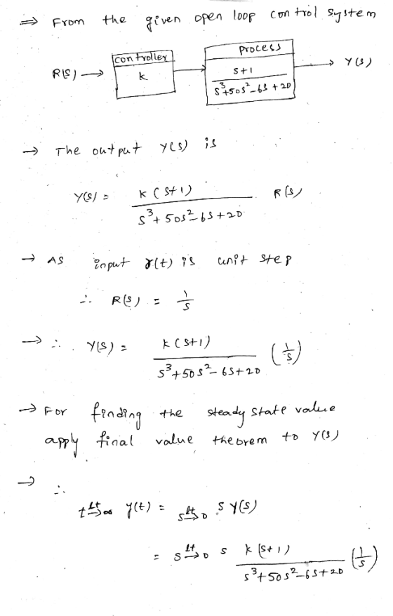
Question 32 For the open-loop control system described by the block diagram shown below, determine the...
yUCni ias the block diagram shown below. Controller Process Sensor (a) (5%) Sketch the root locus of the closed-loop system. (b) (5%) Determine the range of K that the closed-loop system is stabl...
 yUCni ias the block diagram shown below. Controller Process Sensor (a) (5%) Sketch the root locus of the closed-loop system. (b) (5%) Determine the range of K that the closed-loop system is stable. (c) (5%) Find the percentage of overshoot and the steady state error due to a unit step input of the open loop system process. (d) (5%) Find the steady-state error due to a unit step input of the closed-loop syste as a function of the design parameter...
Problem 3 (25%): The closed-loop system has the block diagram shown below. Controlle Process Sensor s + l (a) (5%) Sketch the root locus of the closed-loop system. (b) (5%) Determine the range of...
 Problem 3 (25%): The closed-loop system has the block diagram shown below. Controlle Process Sensor s + l (a) (5%) Sketch the root locus of the closed-loop system. (b) (5%) Determine the range of K that the closed-loop system is stable. (c) (5%) Find the percentage of overshoot and the steady state error due to a unit step input of the open loop system process. (d) (5%) Find the steady-state error due to a unit step input of the closed-loop...
1- Consider the block diagram of a control system shown in Fig. 1 Rts) E ts) C(s) Gt-11027 20s Fi...
 1- Consider the block diagram of a control system shown in Fig. 1 Rts) E ts) C(s) Gt-11027 20s Fig. 1 a) Find the open-loop transfer function of the system. b) Determine the system type and open-loop gain in terms of K and K, c) Find the steady-state errors of the system in terms of K and K,when the following reference inputs are applied: a. Unit ramp reference input: ) b. Parabolic reference input: r()
1- Consider the block diagram...
1- Consider the block diagram of a control system shown in Fig. 1 Rts) E ts) C(s) Gt-11027 20s Fig. 1 a) Find the open-loop transfer function of the system. b) Determine the system type and open-loop gain in terms of K and K, c) Find the steady-state errors of the system in terms of K and K,when the following reference inputs are applied: a. Unit ramp reference input: ) b. Parabolic reference input: r()
1- Consider the block diagram...
Spring 2019 3. Given a closed-loop control system with unity feedback is shown in the block...
 Spring 2019 3. Given a closed-loop control system with unity feedback is shown in the block diagram. G(s) is the open-loop transfer function, and the controller is a gain, K. 1. (20) Calculate the open-loop transfer function tar →Q--t G(s) (10) Calculate the steady-state error to a step input of the open-loop system. 7. (in Bode Form) from the Bode plot. (10) Calculate the shortest possible settling time with a percentage overshoot of 5% or less. 8. 2. (10)Plot the...
Thank You and Thumps Up. For the open loop system shown in the block diagram, sketch...
 Thank You and Thumps Up. For the open loop system shown in the
block diagram, sketch the root-locus for the proportional control.
Design a controller using a pure zero to place the closed-loop
roots in the desired locations shown in the s-plane.
2 5
Thank You and Thumps Up. For the open loop system shown in the
block diagram, sketch the root-locus for the proportional control.
Design a controller using a pure zero to place the closed-loop
roots in the desired locations shown in the s-plane.
2 5
[7] Sketch the root locus for the unity feedback system whose open loop transfer function is K G(s) Draw the root lo...
 [7] Sketch the root locus for the unity feedback system whose open loop transfer function is K G(s) Draw the root locus of the system with the gain Kas a variable. s(s+4) (s2+4s+20) Determine asymptotes, centroid, breakaway point, angle of departure, and the gain at which root locus crosses ja-axis. A control system with type-0 process and a PID controller is shown below. Design the [8 parameters of the PID controller so that the following specifications are satisfied. =100 a)...
1. (30 points) The block diagram of a machine-tool control system is shown in Figure 1. (a) (10 p...
 1. (30 points) The block diagram of a machine-tool control system is shown in Figure 1. (a) (10 points) Determine the transfer function H(s) = Y(s)/R(s) (b) (10 points) Determine the sensitivity S (c) (10 points) For 1
In the block diagram of the feedback control system shown in figure below, Gp(s) is the...
 In the block diagram of the feedback control system shown in figure below, Gp(s) is the transfer function of a process, R(s) is reference input, and A(s) and H(s) represent controllers. N(S) R(s) Gp(s) Process A(s) H(s) = _100_ , and H(s)-1 / GAS). Let Gs)-A(S)5.and Find the steady state value of the response C(t), when N(t) = R(t) = unit-step function. Is this also the maximum value attained by the response? Justify your answers. (s2+2s+4)
control system System Description: The figure 1 and 2 below show, respectively, components and block diagram...
 control system
System Description: The figure 1 and 2 below show, respectively, components and block diagram of a motor and the measurements of velocity (via the tacho unit) and position (via the potentiometer). n represents the gearbox ratio between the rotating shaft and the output shaft. The left-hand side of the diagram represents the controller. A reference set point for the rotating shaft is entered in degrees and this is equivalent voltage. The error is calculated by subtracting the measured...
control system
System Description: The figure 1 and 2 below show, respectively, components and block diagram of a motor and the measurements of velocity (via the tacho unit) and position (via the potentiometer). n represents the gearbox ratio between the rotating shaft and the output shaft. The left-hand side of the diagram represents the controller. A reference set point for the rotating shaft is entered in degrees and this is equivalent voltage. The error is calculated by subtracting the measured...
Problem 8: A control system for an automatic fluid dispenser is shown below: 125 pointsl Y(s) K6s...
 I need the solution using the simulink and if any codes
available please, thanks
Problem 8: A control system for an automatic fluid dispenser is shown below: 125 pointsl Y(s) K6s + 12) Obtain the Closed-loop Transfer Function for the above block diagram. Simulate the system for a unit step input for the following values of K: 15, 30 and 50 On a single graph, plot the response curves for all three cases, for a simulation time of 20 seconds....
I need the solution using the simulink and if any codes
available please, thanks
Problem 8: A control system for an automatic fluid dispenser is shown below: 125 pointsl Y(s) K6s + 12) Obtain the Closed-loop Transfer Function for the above block diagram. Simulate the system for a unit step input for the following values of K: 15, 30 and 50 On a single graph, plot the response curves for all three cases, for a simulation time of 20 seconds....
 yUCni ias the block diagram shown below. Controller Process Sensor (a) (5%) Sketch the root locus of the closed-loop system. (b) (5%) Determine the range of K that the closed-loop system is stable. (c) (5%) Find the percentage of overshoot and the steady state error due to a unit step input of the open loop system process. (d) (5%) Find the steady-state error due to a unit step input of the closed-loop syste as a function of the design parameter...
 Problem 3 (25%): The closed-loop system has the block diagram shown below. Controlle Process Sensor s + l (a) (5%) Sketch the root locus of the closed-loop system. (b) (5%) Determine the range of K that the closed-loop system is stable. (c) (5%) Find the percentage of overshoot and the steady state error due to a unit step input of the open loop system process. (d) (5%) Find the steady-state error due to a unit step input of the closed-loop...
 1- Consider the block diagram of a control system shown in Fig. 1 Rts) E ts) C(s) Gt-11027 20s Fig. 1 a) Find the open-loop transfer function of the system. b) Determine the system type and open-loop gain in terms of K and K, c) Find the steady-state errors of the system in terms of K and K,when the following reference inputs are applied: a. Unit ramp reference input: ) b. Parabolic reference input: r()
1- Consider the block diagram...
1- Consider the block diagram of a control system shown in Fig. 1 Rts) E ts) C(s) Gt-11027 20s Fig. 1 a) Find the open-loop transfer function of the system. b) Determine the system type and open-loop gain in terms of K and K, c) Find the steady-state errors of the system in terms of K and K,when the following reference inputs are applied: a. Unit ramp reference input: ) b. Parabolic reference input: r()
1- Consider the block diagram...
 Spring 2019 3. Given a closed-loop control system with unity feedback is shown in the block diagram. G(s) is the open-loop transfer function, and the controller is a gain, K. 1. (20) Calculate the open-loop transfer function tar →Q--t G(s) (10) Calculate the steady-state error to a step input of the open-loop system. 7. (in Bode Form) from the Bode plot. (10) Calculate the shortest possible settling time with a percentage overshoot of 5% or less. 8. 2. (10)Plot the...
 Thank You and Thumps Up. For the open loop system shown in the
block diagram, sketch the root-locus for the proportional control.
Design a controller using a pure zero to place the closed-loop
roots in the desired locations shown in the s-plane.
2 5
Thank You and Thumps Up. For the open loop system shown in the
block diagram, sketch the root-locus for the proportional control.
Design a controller using a pure zero to place the closed-loop
roots in the desired locations shown in the s-plane.
2 5
 [7] Sketch the root locus for the unity feedback system whose open loop transfer function is K G(s) Draw the root locus of the system with the gain Kas a variable. s(s+4) (s2+4s+20) Determine asymptotes, centroid, breakaway point, angle of departure, and the gain at which root locus crosses ja-axis. A control system with type-0 process and a PID controller is shown below. Design the [8 parameters of the PID controller so that the following specifications are satisfied. =100 a)...
 1. (30 points) The block diagram of a machine-tool control system is shown in Figure 1. (a) (10 points) Determine the transfer function H(s) = Y(s)/R(s) (b) (10 points) Determine the sensitivity S (c) (10 points) For 1
 In the block diagram of the feedback control system shown in figure below, Gp(s) is the transfer function of a process, R(s) is reference input, and A(s) and H(s) represent controllers. N(S) R(s) Gp(s) Process A(s) H(s) = _100_ , and H(s)-1 / GAS). Let Gs)-A(S)5.and Find the steady state value of the response C(t), when N(t) = R(t) = unit-step function. Is this also the maximum value attained by the response? Justify your answers. (s2+2s+4)
 control system
System Description: The figure 1 and 2 below show, respectively, components and block diagram of a motor and the measurements of velocity (via the tacho unit) and position (via the potentiometer). n represents the gearbox ratio between the rotating shaft and the output shaft. The left-hand side of the diagram represents the controller. A reference set point for the rotating shaft is entered in degrees and this is equivalent voltage. The error is calculated by subtracting the measured...
control system
System Description: The figure 1 and 2 below show, respectively, components and block diagram of a motor and the measurements of velocity (via the tacho unit) and position (via the potentiometer). n represents the gearbox ratio between the rotating shaft and the output shaft. The left-hand side of the diagram represents the controller. A reference set point for the rotating shaft is entered in degrees and this is equivalent voltage. The error is calculated by subtracting the measured...
 I need the solution using the simulink and if any codes
available please, thanks
Problem 8: A control system for an automatic fluid dispenser is shown below: 125 pointsl Y(s) K6s + 12) Obtain the Closed-loop Transfer Function for the above block diagram. Simulate the system for a unit step input for the following values of K: 15, 30 and 50 On a single graph, plot the response curves for all three cases, for a simulation time of 20 seconds....
I need the solution using the simulink and if any codes
available please, thanks
Problem 8: A control system for an automatic fluid dispenser is shown below: 125 pointsl Y(s) K6s + 12) Obtain the Closed-loop Transfer Function for the above block diagram. Simulate the system for a unit step input for the following values of K: 15, 30 and 50 On a single graph, plot the response curves for all three cases, for a simulation time of 20 seconds....
Most questions answered within 3 hours.
-
Is the globalization of health care good or bad for patients?
Who might benefit from the...
asked 6 seconds from now -
Is the dissolution of the salt A(OH)2 a reaction that increases
the disorder, or decreases the...
asked 42 seconds ago -
A new president at Big State University has made student
satisfaction with the enrollment and registration...
asked 57 seconds ago -
Edwards and Bell market a single line of home computer, dubbed
the XL-98. The master budget...
asked 1 minute ago -
Given the following list of objects and a fixed bin size of
70:
L = [16,...
asked 25 minutes ago -
A mixture of 0.500 mols of NO and 0.100 mols O2 are combined in
a 5...
asked 22 minutes ago -
A city contains 150,000 people (80,000 females and 70,000
males), and 1,500 people die per year...
asked 20 minutes ago -
A certain weak base has a Kb of 8.80×10⁻⁷. What concentration of
this base will produce...
asked 23 minutes ago -
Suppose that the average U.S. household uses 12100 kWh
(kilowatt‑hours) of energy in a year. If...
asked 30 minutes ago -
Patterson Company operates three segments. Income statements for
the segments imply that profitability could be improved...
asked 30 minutes ago -
In 20 words or less, what aspect of your degree course are you
passionate about? civil...
asked 41 minutes ago -
Learning Goal: To understand the relation between the strength
of an acid or a base and...
asked 43 minutes ago