
Homework Answers

Add Answer to:
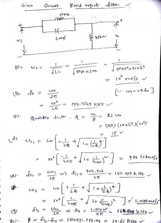
2. For the bandreject filter shown below, find (a) Wo, (b) fo, (e) Q. (d) Wel,...
Homework #2 Problem 14.38 PSpice Multisim Part A Consider the bandreject filter shown in (Figure 1)....
 Homework #2 Problem 14.38 PSpice Multisim Part A Consider the bandreject filter shown in (Figure 1). Suppose that R-4 k2,L-3.5 mH, C-62.5 nF Calculate the center frequency wo. Express your answer using three significant figures vec krad/s Figure 1 of 1 Submit Request Answen Part B Calculate the center frequency f, in kilohertz. Express your answer using three significant figures vec kHz Problem 14.38 PSpice Multisim Part C Consider the bandreject filter shown in (Figure 1). Suppose that R-4 k2,L-3.5...
Problem 2 a) Using 5 nF capacitors, design an active broad- band first-order bandreject filter with...
Problem 2 a) Using 5 nF capacitors, design an active broad- band first-order bandreject filter with a lower cutoff frequency of 1000 Hz, an upper cut-off frequency of 5000 Hz, and a pass band gain of 10dB. b) Draw the schematic diagram of the filter. c) Write the transfer function to find H(jωo), where ωo is the center frequency of the filter. d) What is the gain (in decibels) of the filer at the center frequency? e) Using Matlab make...
Problem 14.18 PSpice Multisim Part C Find Q For the bandpass filter shown the fiqure R 9 kSn,C 8 ...
 Problem 14.18 PSpice Multisim Part C Find Q For the bandpass filter shown the fiqure R 9 kSn,C 8 nF , and L = 12mH (Figure 1) vec Q0.136083 Figure 1 of 1> SubmitPre ious Ans Request Answer X Incorrect; Try Again; 3 attempts remaining ▼ Part D Find wel vec krad/s cl Problem 14.18 PSpice Multisim Part E k2, C 8 For the bandpass filter shown the figure R nF, and L 12 mHH (Figure 1) 9 Find fal...
7. (20 points) The loop filter of the second-order digital PLL shown below is given by...
 7. (20 points) The loop filter of the second-order digital PLL shown below is given by F(2) The DPLL is called two-poles. Assume that a = 0.2, b = 0.15. bz-1 = 1-az-1° O(z) E(z) Loop Filter F(z) 6(z) VCO Z 1-z-1 (a) Find the closed-loop transfer function H(z). (b) Find the impulse response h(n) and plot h(n). (c) Find the step response hș(n) and plot hs(n). (d) Find the ramp response hr(n) and plot hr(n). (e) Find the steady...
100 Consider the following LTI system, 5, and wo = 2000π rad/sec. where, Q a) Use MATLAB to deter...
 please complete this project.
100 Consider the following LTI system, 5, and wo = 2000π rad/sec. where, Q a) Use MATLAB to determine magnitude response and phase response of the filter b) What type of filter is it? c) What will be the output of this filter if input x,(t)-5Cos(100t). Show all calculations step by step as shown in Lecture-20 d) Verify your answer of part (e) by using Simulink model. Attach the snapshot of Simulink model and output e)...
please complete this project.
100 Consider the following LTI system, 5, and wo = 2000π rad/sec. where, Q a) Use MATLAB to determine magnitude response and phase response of the filter b) What type of filter is it? c) What will be the output of this filter if input x,(t)-5Cos(100t). Show all calculations step by step as shown in Lecture-20 d) Verify your answer of part (e) by using Simulink model. Attach the snapshot of Simulink model and output e)...
Consider the circuit below. Using Fourier transform analysis: 192 (a) Find the transfer function H(o)=V.(0V:(0). (b)...
 Consider the circuit below. Using Fourier transform analysis: 192 (a) Find the transfer function H(o)=V.(0V:(0). (b) Determine the type of the filter (justify your IF answer). (c) If the filter is a bandpass or a bandreject, calculate its center frequency. (d) Calculate the cutoff frequency (or frequencies) of the filter CE } 2H
R1 = 49.7 Ohms, C1 = 1.60 uF Using the circuit shown in (Figure 1), design a narrow band bandreject filter having a center frequency of 4 kHz and a quality factor of 10. Base the design on igure 1 of...
 R1 = 49.7 Ohms, C1 = 1.60 uF
Using the circuit shown in (Figure 1), design a narrow band bandreject filter having a center frequency of 4 kHz and a quality factor of 10. Base the design on igure 1 of 2 (> (1-o)R Figure 2 of 2 l6 RI R3 RC 2 Rs Part C Determine the resistance R2 in the filter Express your answer to three significant figures and include the appropriate units R2Value Units Submit Request Answer...
R1 = 49.7 Ohms, C1 = 1.60 uF
Using the circuit shown in (Figure 1), design a narrow band bandreject filter having a center frequency of 4 kHz and a quality factor of 10. Base the design on igure 1 of 2 (> (1-o)R Figure 2 of 2 l6 RI R3 RC 2 Rs Part C Determine the resistance R2 in the filter Express your answer to three significant figures and include the appropriate units R2Value Units Submit Request Answer...
Problem 1. Find and sketch (see below) the impulse response of the ideal bandpass filter whose fr...
 Problem 1. Find and sketch (see below) the impulse response of the ideal bandpass filter whose frequency response is shown below Hints: Consider Hf)- H(f) 6f -fc) +(f+fo). . Convolution in one domain is ·To sketch, use fc = 2 Hz and W = 0.5 Hz. in the other domain. H(f) Ic -w fc c +w Figure 1: Ideal bandpass filter frequency response for Problem
Problem 1. Find and sketch (see below) the impulse response of the ideal bandpass filter...
Problem 1. Find and sketch (see below) the impulse response of the ideal bandpass filter whose frequency response is shown below Hints: Consider Hf)- H(f) 6f -fc) +(f+fo). . Convolution in one domain is ·To sketch, use fc = 2 Hz and W = 0.5 Hz. in the other domain. H(f) Ic -w fc c +w Figure 1: Ideal bandpass filter frequency response for Problem
Problem 1. Find and sketch (see below) the impulse response of the ideal bandpass filter...
2. The KHN universal biquad filter shown below has the following transfer function for the high-pass...
 2. The KHN universal biquad filter shown below has the following transfer function for the high-pass terminal. This filter is designed such that w, = 10 krad/s, Q = 2. a. Does this filter have humps? Why? b. Find the 3-dB bandwidth of the bandpass filter terminal, Vbp. 3++ - (,%) 0.707 -- - (O/V2w) ( 0) 02
12. For an F distribution, find the following: (a) fo.25,5,10 (b) fo.10.c)o.05,8,15 (d) o.75,5,10 (e)fo.so, (f)fo.95,8,15...
 12. For an F distribution, find the following: (a) fo.25,5,10 (b) fo.10.c)o.05,8,15 (d) o.75,5,10 (e)fo.so, (f)fo.95,8,15 0.10,24,9 0.90.24,9
 Homework #2 Problem 14.38 PSpice Multisim Part A Consider the bandreject filter shown in (Figure 1). Suppose that R-4 k2,L-3.5 mH, C-62.5 nF Calculate the center frequency wo. Express your answer using three significant figures vec krad/s Figure 1 of 1 Submit Request Answen Part B Calculate the center frequency f, in kilohertz. Express your answer using three significant figures vec kHz Problem 14.38 PSpice Multisim Part C Consider the bandreject filter shown in (Figure 1). Suppose that R-4 k2,L-3.5...
 Problem 14.18 PSpice Multisim Part C Find Q For the bandpass filter shown the fiqure R 9 kSn,C 8 nF , and L = 12mH (Figure 1) vec Q0.136083 Figure 1 of 1> SubmitPre ious Ans Request Answer X Incorrect; Try Again; 3 attempts remaining ▼ Part D Find wel vec krad/s cl Problem 14.18 PSpice Multisim Part E k2, C 8 For the bandpass filter shown the figure R nF, and L 12 mHH (Figure 1) 9 Find fal...
 7. (20 points) The loop filter of the second-order digital PLL shown below is given by F(2) The DPLL is called two-poles. Assume that a = 0.2, b = 0.15. bz-1 = 1-az-1° O(z) E(z) Loop Filter F(z) 6(z) VCO Z 1-z-1 (a) Find the closed-loop transfer function H(z). (b) Find the impulse response h(n) and plot h(n). (c) Find the step response hș(n) and plot hs(n). (d) Find the ramp response hr(n) and plot hr(n). (e) Find the steady...
 please complete this project.
100 Consider the following LTI system, 5, and wo = 2000π rad/sec. where, Q a) Use MATLAB to determine magnitude response and phase response of the filter b) What type of filter is it? c) What will be the output of this filter if input x,(t)-5Cos(100t). Show all calculations step by step as shown in Lecture-20 d) Verify your answer of part (e) by using Simulink model. Attach the snapshot of Simulink model and output e)...
please complete this project.
100 Consider the following LTI system, 5, and wo = 2000π rad/sec. where, Q a) Use MATLAB to determine magnitude response and phase response of the filter b) What type of filter is it? c) What will be the output of this filter if input x,(t)-5Cos(100t). Show all calculations step by step as shown in Lecture-20 d) Verify your answer of part (e) by using Simulink model. Attach the snapshot of Simulink model and output e)...
 Consider the circuit below. Using Fourier transform analysis: 192 (a) Find the transfer function H(o)=V.(0V:(0). (b) Determine the type of the filter (justify your IF answer). (c) If the filter is a bandpass or a bandreject, calculate its center frequency. (d) Calculate the cutoff frequency (or frequencies) of the filter CE } 2H
 R1 = 49.7 Ohms, C1 = 1.60 uF
Using the circuit shown in (Figure 1), design a narrow band bandreject filter having a center frequency of 4 kHz and a quality factor of 10. Base the design on igure 1 of 2 (> (1-o)R Figure 2 of 2 l6 RI R3 RC 2 Rs Part C Determine the resistance R2 in the filter Express your answer to three significant figures and include the appropriate units R2Value Units Submit Request Answer...
R1 = 49.7 Ohms, C1 = 1.60 uF
Using the circuit shown in (Figure 1), design a narrow band bandreject filter having a center frequency of 4 kHz and a quality factor of 10. Base the design on igure 1 of 2 (> (1-o)R Figure 2 of 2 l6 RI R3 RC 2 Rs Part C Determine the resistance R2 in the filter Express your answer to three significant figures and include the appropriate units R2Value Units Submit Request Answer...
 Problem 1. Find and sketch (see below) the impulse response of the ideal bandpass filter whose frequency response is shown below Hints: Consider Hf)- H(f) 6f -fc) +(f+fo). . Convolution in one domain is ·To sketch, use fc = 2 Hz and W = 0.5 Hz. in the other domain. H(f) Ic -w fc c +w Figure 1: Ideal bandpass filter frequency response for Problem
Problem 1. Find and sketch (see below) the impulse response of the ideal bandpass filter...
Problem 1. Find and sketch (see below) the impulse response of the ideal bandpass filter whose frequency response is shown below Hints: Consider Hf)- H(f) 6f -fc) +(f+fo). . Convolution in one domain is ·To sketch, use fc = 2 Hz and W = 0.5 Hz. in the other domain. H(f) Ic -w fc c +w Figure 1: Ideal bandpass filter frequency response for Problem
Problem 1. Find and sketch (see below) the impulse response of the ideal bandpass filter...
 2. The KHN universal biquad filter shown below has the following transfer function for the high-pass terminal. This filter is designed such that w, = 10 krad/s, Q = 2. a. Does this filter have humps? Why? b. Find the 3-dB bandwidth of the bandpass filter terminal, Vbp. 3++ - (,%) 0.707 -- - (O/V2w) ( 0) 02
 12. For an F distribution, find the following: (a) fo.25,5,10 (b) fo.10.c)o.05,8,15 (d) o.75,5,10 (e)fo.so, (f)fo.95,8,15 0.10,24,9 0.90.24,9
Most questions answered within 3 hours.
-
Humans have used horses for transportation for millions of
years. Therefore, they will use horses for...
asked 55 minutes ago -
The following are the Jensen Corporation's unit costs of making
and selling an item at a...
asked 1 hour ago -
Does direct Medicare reimbursement of Advanced practice nurses
increase access to their services?
asked 2 hours ago -
List and explain why a company would choose to use a
published
compensation survey vs. creating...
asked 2 hours ago -
A discrete random variable X can take values from 1 to 10. Find
the variance of...
asked 2 hours ago -
The primary financial goal of a corporation is to maximize:
shareholders wealth.
earnings per share.
stock...
asked 2 hours ago -
determine whether the vectors u=(1,2,3,), v=(-2,1,0) and
w=(1,0,1) are linearly dependent or independent.
asked 2 hours ago -
python
Define a function called print_values which takes a dictionary
object as a parameter. The function...
asked 3 hours ago -
In Chapter 1 you created a program named Triangle in
which you displayed a seven-line triangle...
asked 3 hours ago -
Research question: What are the differences between separately
stated and non separately stated transactions in an...
asked 4 hours ago -
By using Arduino write a code that connects two LEDs to two
push-buttons. Each button controls...
asked 5 hours ago -
Bank of America has bonds that pay a coupon interest rate of 5.5
percent and mature...
asked 6 hours ago