Isometric Projection is an engineering technique used to represent 3 Dimensions in 2D. ( With the...

Isometric Projection is an engineering technique used to represent 3 Dimensions in 2D. ( With the correct angle and projection) thank you
Homework Answers
Isometric view:


Steps: (solving using the solid work software)
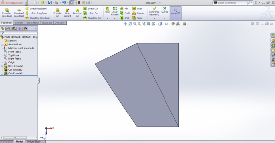
1. Draw a new sketch on the front plane shown below, then extrude it to 4 units.


2. Draw a new sketch on the top face shown below, then extrude cut it through all.


3. Again create a new sketch on the top face, and extrude cut to 1 unit.


5. The finished part and standard views:


Isometric view-

Add Answer to:
Isometric Projection is an engineering technique used to
represent 3 Dimensions in 2D. ( With the...
1. An orthogonal projection of an object in a 2D drawing of an object as it...
 1. An orthogonal projection of an object in a 2D drawing of an object as it would appear with all its feature projected perpendicular to a viewing..True? a. Yes b. No The concept of 'glass box' is used in connection with: Orthographic projection b, 3rd angle projection c. Multiview representations d. all of the above 2. a. When the top view is placed above the front view on a drav g, the following is true? a. It does not conform...
Please explain the steps properly 3. Draw the Isometric projection for the given orthographic 30 angle...
 Please explain the steps properly
3. Draw the Isometric projection for the given orthographic 30 angle view. 45 50 30 80 -30 Manipal International University, Malaysia
Please explain the steps properly
3. Draw the Isometric projection for the given orthographic 30 angle view. 45 50 30 80 -30 Manipal International University, Malaysia
Please help me answer this question. Thank you so much 04-BS-15 Engineering Graphics & Design Process...
 Please help me answer this question. Thank you so much
04-BS-15 Engineering Graphics & Design Process May 2014 2. Sketch an isometric pictorial of the following orthographic projection not draw. Do not use a straight edge. Sketch. Do Criterion Grade Isometric pictorial 4: Correct angles of horizontal lines 3: Near correct angles of horizontal lines 0: Not an isometric pictorial 4: Flawless 3: Minor errors 2: One or more significant omissions 1/0: Part could not be manufactured projection Penalties -10:...
Please help me answer this question. Thank you so much
04-BS-15 Engineering Graphics & Design Process May 2014 2. Sketch an isometric pictorial of the following orthographic projection not draw. Do not use a straight edge. Sketch. Do Criterion Grade Isometric pictorial 4: Correct angles of horizontal lines 3: Near correct angles of horizontal lines 0: Not an isometric pictorial 4: Flawless 3: Minor errors 2: One or more significant omissions 1/0: Part could not be manufactured projection Penalties -10:...
When undertaking the isometric routing of pipe, what are any six main considerations used to ensure...
When undertaking the isometric routing of pipe, what are any six main considerations used to ensure you will achieve a perfect isometric routing on a sample pipe work? Hint: Consider vertical vs. horizontal design and its relation to elevations, also designating different engineering disciplines (such as electrical, instrumentation, mechanical, ...) to the piping installation to get more clear roles and definitions for different pipe racks and supports, also consider the role of gaskets and flanges and the way they are...
With dimensions please ALL FOUR . Thank you, Department of Mechanical Engineering Part-1 (Orthographic Projections) Extract...
 With dimensions please ALL FOUR .
Thank you,
Department of Mechanical Engineering Part-1 (Orthographic Projections) Extract the standard views using third angle proiection for the following problems. 80 25 i0 110 R S0 150 70 70 R.20 4.00 40 70 0 404 150
With dimensions please ALL FOUR .
Thank you,
Department of Mechanical Engineering Part-1 (Orthographic Projections) Extract the standard views using third angle proiection for the following problems. 80 25 i0 110 R S0 150 70 70 R.20 4.00 40 70 0 404 150
Please help answer this question? Please note that no dimensions were provided. Thank you so much
 Please help answer this question? Please note that no dimensions
were provided.
Thank you so much
04-BS-15 Engineering Graphics & Design Process December 2018 QUESTION 1 (50 MARKS) For the part shown below, Sketch an appropriate set of orthographic views, using third-angle projection. (10 marks) Fully dimension the sketch in part a) using professional standards. Use "xx" in place of numerical values in the dimensions. (10 marks) Describe and sketch an appropriate sequence of feature-based solid modelling operations that could...
Please help answer this question? Please note that no dimensions
were provided.
Thank you so much
04-BS-15 Engineering Graphics & Design Process December 2018 QUESTION 1 (50 MARKS) For the part shown below, Sketch an appropriate set of orthographic views, using third-angle projection. (10 marks) Fully dimension the sketch in part a) using professional standards. Use "xx" in place of numerical values in the dimensions. (10 marks) Describe and sketch an appropriate sequence of feature-based solid modelling operations that could...
Please help me answer this question? Please note that no dimensions were given. Thank you so much
 Please help me answer this question? Please note that no
dimensions were given. Thank you so much
04-BS-15 Engineering Graphics & Design Process May 2012 QUESTION 1 For the part shown below, Sketch an appropriate set of orthographic views, using third-angle projection. (10 marks) values in the dimensions. (10 marks) could be used to create this geometry using parametric, feature-based solid modelling CAD a) b) Fully dimension the sketch in part a) using professional standards. Use "xx' in place of...
Please help me answer this question? Please note that no
dimensions were given. Thank you so much
04-BS-15 Engineering Graphics & Design Process May 2012 QUESTION 1 For the part shown below, Sketch an appropriate set of orthographic views, using third-angle projection. (10 marks) values in the dimensions. (10 marks) could be used to create this geometry using parametric, feature-based solid modelling CAD a) b) Fully dimension the sketch in part a) using professional standards. Use "xx' in place of...
04-BS-15 Engineering Graphics & Design Process May 2012 QUESTION 1 For the part shown below, Sketch an appropriate set of orthographic views, using third-angle projection. (10 marks) values in th...
 04-BS-15 Engineering Graphics & Design Process May 2012 QUESTION 1 For the part shown below, Sketch an appropriate set of orthographic views, using third-angle projection. (10 marks) values in the dimensions. (10 marks) could be used to create this geometry using parametric, feature-based solid modelling CAD a) b) Fully dimension the sketch in part a) using professional standards. Use "xx' in place of numerical c) Describe and sketch an appropriate sequence of feature-based solid modelling operations that d) Describe and...
02/ Two objects that are to be fitted together by a fastener such as a screw-and-n combination. For this problem, a cylinder will be used to represent a fastener. Onl dimensions are given. a- What ar...
 02/ Two objects that are to be fitted together by a fastener such as a screw-and-n combination. For this problem, a cylinder will be used to represent a fastener. Onl dimensions are given. a- What are the dimensions and tolerances if you assume that the hol and the clearance was assigned to be 0.01? b- What are the dimensions and tolerances for the Fixed Condition? e tolerance is 0.01 FASTENER Floating condition The distance between the holes is 50 part...
3rd Angle Projection. Sketch the dimensions without over dimensioning. Date Unit 9 Dimensioning 187 Name Class...
 3rd Angle Projection. Sketch the dimensions without over
dimensioning.
Date Unit 9 Dimensioning 187 Name Class Review Activity 9-1 dad the dimensions required to completely describe the size of the block shown below without over dimensioning. esible discuss the choice and placement with others to evaluate the available options. Your instructor will te whether or not you should use mal number values and metsurements or simply se "X" for the number les to focus on the mechanics and the choice...
3rd Angle Projection. Sketch the dimensions without over
dimensioning.
Date Unit 9 Dimensioning 187 Name Class Review Activity 9-1 dad the dimensions required to completely describe the size of the block shown below without over dimensioning. esible discuss the choice and placement with others to evaluate the available options. Your instructor will te whether or not you should use mal number values and metsurements or simply se "X" for the number les to focus on the mechanics and the choice...
 1. An orthogonal projection of an object in a 2D drawing of an object as it would appear with all its feature projected perpendicular to a viewing..True? a. Yes b. No The concept of 'glass box' is used in connection with: Orthographic projection b, 3rd angle projection c. Multiview representations d. all of the above 2. a. When the top view is placed above the front view on a drav g, the following is true? a. It does not conform...
 Please explain the steps properly
3. Draw the Isometric projection for the given orthographic 30 angle view. 45 50 30 80 -30 Manipal International University, Malaysia
Please explain the steps properly
3. Draw the Isometric projection for the given orthographic 30 angle view. 45 50 30 80 -30 Manipal International University, Malaysia
 Please help me answer this question. Thank you so much
04-BS-15 Engineering Graphics & Design Process May 2014 2. Sketch an isometric pictorial of the following orthographic projection not draw. Do not use a straight edge. Sketch. Do Criterion Grade Isometric pictorial 4: Correct angles of horizontal lines 3: Near correct angles of horizontal lines 0: Not an isometric pictorial 4: Flawless 3: Minor errors 2: One or more significant omissions 1/0: Part could not be manufactured projection Penalties -10:...
Please help me answer this question. Thank you so much
04-BS-15 Engineering Graphics & Design Process May 2014 2. Sketch an isometric pictorial of the following orthographic projection not draw. Do not use a straight edge. Sketch. Do Criterion Grade Isometric pictorial 4: Correct angles of horizontal lines 3: Near correct angles of horizontal lines 0: Not an isometric pictorial 4: Flawless 3: Minor errors 2: One or more significant omissions 1/0: Part could not be manufactured projection Penalties -10:...
 With dimensions please ALL FOUR .
Thank you,
Department of Mechanical Engineering Part-1 (Orthographic Projections) Extract the standard views using third angle proiection for the following problems. 80 25 i0 110 R S0 150 70 70 R.20 4.00 40 70 0 404 150
With dimensions please ALL FOUR .
Thank you,
Department of Mechanical Engineering Part-1 (Orthographic Projections) Extract the standard views using third angle proiection for the following problems. 80 25 i0 110 R S0 150 70 70 R.20 4.00 40 70 0 404 150
 Please help answer this question? Please note that no dimensions
were provided.
Thank you so much
04-BS-15 Engineering Graphics & Design Process December 2018 QUESTION 1 (50 MARKS) For the part shown below, Sketch an appropriate set of orthographic views, using third-angle projection. (10 marks) Fully dimension the sketch in part a) using professional standards. Use "xx" in place of numerical values in the dimensions. (10 marks) Describe and sketch an appropriate sequence of feature-based solid modelling operations that could...
Please help answer this question? Please note that no dimensions
were provided.
Thank you so much
04-BS-15 Engineering Graphics & Design Process December 2018 QUESTION 1 (50 MARKS) For the part shown below, Sketch an appropriate set of orthographic views, using third-angle projection. (10 marks) Fully dimension the sketch in part a) using professional standards. Use "xx" in place of numerical values in the dimensions. (10 marks) Describe and sketch an appropriate sequence of feature-based solid modelling operations that could...
 Please help me answer this question? Please note that no
dimensions were given. Thank you so much
04-BS-15 Engineering Graphics & Design Process May 2012 QUESTION 1 For the part shown below, Sketch an appropriate set of orthographic views, using third-angle projection. (10 marks) values in the dimensions. (10 marks) could be used to create this geometry using parametric, feature-based solid modelling CAD a) b) Fully dimension the sketch in part a) using professional standards. Use "xx' in place of...
Please help me answer this question? Please note that no
dimensions were given. Thank you so much
04-BS-15 Engineering Graphics & Design Process May 2012 QUESTION 1 For the part shown below, Sketch an appropriate set of orthographic views, using third-angle projection. (10 marks) values in the dimensions. (10 marks) could be used to create this geometry using parametric, feature-based solid modelling CAD a) b) Fully dimension the sketch in part a) using professional standards. Use "xx' in place of...
 04-BS-15 Engineering Graphics & Design Process May 2012 QUESTION 1 For the part shown below, Sketch an appropriate set of orthographic views, using third-angle projection. (10 marks) values in the dimensions. (10 marks) could be used to create this geometry using parametric, feature-based solid modelling CAD a) b) Fully dimension the sketch in part a) using professional standards. Use "xx' in place of numerical c) Describe and sketch an appropriate sequence of feature-based solid modelling operations that d) Describe and...
 02/ Two objects that are to be fitted together by a fastener such as a screw-and-n combination. For this problem, a cylinder will be used to represent a fastener. Onl dimensions are given. a- What are the dimensions and tolerances if you assume that the hol and the clearance was assigned to be 0.01? b- What are the dimensions and tolerances for the Fixed Condition? e tolerance is 0.01 FASTENER Floating condition The distance between the holes is 50 part...
 3rd Angle Projection. Sketch the dimensions without over
dimensioning.
Date Unit 9 Dimensioning 187 Name Class Review Activity 9-1 dad the dimensions required to completely describe the size of the block shown below without over dimensioning. esible discuss the choice and placement with others to evaluate the available options. Your instructor will te whether or not you should use mal number values and metsurements or simply se "X" for the number les to focus on the mechanics and the choice...
3rd Angle Projection. Sketch the dimensions without over
dimensioning.
Date Unit 9 Dimensioning 187 Name Class Review Activity 9-1 dad the dimensions required to completely describe the size of the block shown below without over dimensioning. esible discuss the choice and placement with others to evaluate the available options. Your instructor will te whether or not you should use mal number values and metsurements or simply se "X" for the number les to focus on the mechanics and the choice...
Most questions answered within 3 hours.
-
A manufacturing company preparing to build a new plant is
considering three potential locations for it....
asked 1 minute from now -
B. If compound Y has approximately the same values of solubility
in toluene as compound X,...
asked 44 minutes ago -
Oscar Inc. has inventory in Japan valued at 39,051,000 Yen one
year ago. One year ago...
asked 51 minutes ago -
If Canada suffered from "fundamental disequilibrium," and its
government choose not to devalue its currency, a...
asked 1 hour ago -
4. How many input & output Key Value Pairs are passed into,
and emitted out of...
asked 55 minutes ago -
Why would your heart not function well if constructed of
skeletal muscle? What is the particular...
asked 1 hour ago -
Please respond to this essay question in full essay form for
Chemistry 1102 Organic and Biochemistry:...
asked 1 hour ago -
Determine the head loss and velocity of flow in a water supply main
of 15.0 cm...
asked 1 hour ago -
A marketing executive who knowingly authorizes a shoddy
defective product to be brought to market is...
asked 1 hour ago -
Write a psudocode:
1. Define a function called authorize that takes in 2 strings,
uName, and...
asked 1 hour ago -
What Hall voltage (in mV) is produced by a 0.180 T field applied
across a 2.60...
asked 1 hour ago -
What mass of ethylene glycol (C2H6O2) must be added to 211.0 g
of water to obtain...
asked 1 hour ago