
Homework Answers
Add Answer to:
Consider the system shown in the following. Determine the value of k such that the damping...
Topic: Second order system 4. pts) For the linear system with a block diagram shown: a....
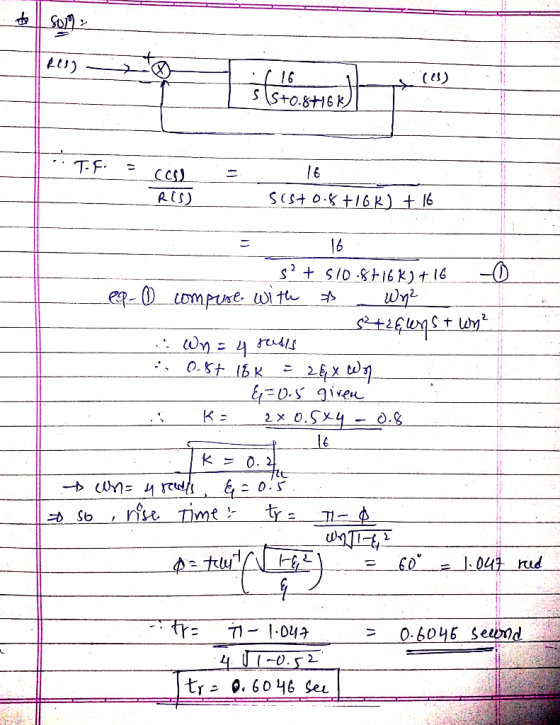
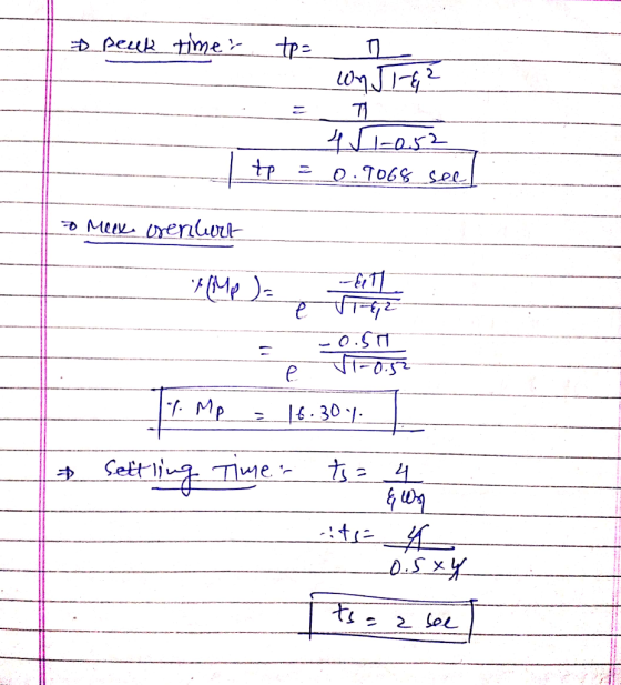
 Topic: Second order system 4. pts) For the linear system with a block diagram shown: a. Find the closed loop transfer function C(s)/R(s) b. Find the value of K and the location of the poles C(s) R(s) for a damping ratio equal to 0.5 S+0.8 c. When the input is a unit-step and the damping ratio is 0.5 Find Peak Time (Tp), Maximum Overshoot (Mp) and Settling Time (Ts)
please help to solve this. Thank you B1. Consider the second order system where damping ratio...
 please help to solve this. Thank you
B1. Consider the second order system where damping ratio 3-0.6 and natural angular frequency Ww=5 rad/sec. find the rise time tr, peak time tp, maximum overshoot Mp, and settling time ts (2%) when the system is subjected to a unit-step input. I B2. Find the steady-state errors for inputs of 5 u(t), 5t u(t), and 5t.u(t) to the system shown in the following figure. The function u(t) is the unit step. R(S) +...
please help to solve this. Thank you
B1. Consider the second order system where damping ratio 3-0.6 and natural angular frequency Ww=5 rad/sec. find the rise time tr, peak time tp, maximum overshoot Mp, and settling time ts (2%) when the system is subjected to a unit-step input. I B2. Find the steady-state errors for inputs of 5 u(t), 5t u(t), and 5t.u(t) to the system shown in the following figure. The function u(t) is the unit step. R(S) +...
Question 2 a) Consider the control system in Figure 2(a). Determine the transient response characteristics (rise...
 Question 2 a) Consider the control system in Figure 2(a). Determine the transient response characteristics (rise time, peak time, maximum overshoot and settling time) and the steady state error for the system. (2 marks) b) To improve the relative stability, the tachometer feedback are employed as shown in Figure 2b). i Determine the value in so that the damping ratio of the system is 0.5. (1 % marks) From the result obtained in , evaluate the transient response characteristics (rise...
a) Consider the control system in Figure 2(a). Determine the transient response characteristics (rise time, peak...
 a) Consider the control system in Figure 2(a). Determine the transient response characteristics (rise time, peak time, maximum overshoot and settling time) and the steady state error for the system. (2 marks) b) To improve the relative stability, the tachometer feedback are employed as shown in Figure 2(b). i Determine the value K, so that the damping ratio of the system is 0.5. (1 % marks) ii. From the result obtained in (), evaluate the transient response characteristics (rise time,...
a) Consider the control system in Figure 2(a). Determine the transient response characteristics (rise time, peak...
 a) Consider the control system in Figure 2(a). Determine the transient response characteristics (rise time, peak time, maximum overshoot and settling time) and the steady state error for the system. (2 marks) b) To improve the relative stability, the tachometer feedback are employed as shown in Figure 2(b). i. Determine the value Kn so that the damping ratio of the system is 0.5. (1 22 marks) ii. iii. From the result obtained in (i), evaluate the transient response characteristics (rise...
Question 2 a) Consider the control system in Figure 2(a). Determine the transient response characteristics (rise...
 Question 2 a) Consider the control system in Figure 2(a). Determine the transient response characteristics (rise time, peak time, maximum overshoot and settling time) and the steady state error for the system. (2 marks) b) To improve the relative stability, the tachometer feedback are employed as shown in Figure 2(b). Determine the value K, so that the damping ratio of the system is 0.5. (1 % marks) i. From the result obtained in (), evaluate the transient response characteristics (rise...
Question 2 a) Consider the control system in Figure 2(a). Determine the transient response characteristics (rise...
 Question 2 a) Consider the control system in Figure 2(a). Determine the transient response characteristics (rise time, peak time, maximum overshoot and settling time) and the steady state error for the system. (2 marks) b) To improve the relative stability, the tachometer feedback are employed as shown in Figure 2(b). i Determine the value Kso that the damping ratio of the system is 0.5. (1 % marks) i. From the result obtained in (), evaluate the transient response characteristics (rise...
. a) Consider the control system in Figure 2(a). Determine the transient response characteristics (rise time,...
 .
a) Consider the control system in Figure 2(a). Determine the transient response characteristics (rise time, peak time, maximum overshoot and settling time) and the steady state error for the system. (2 marks) b) To improve the relative stability, the tachometer feedback are employed as shown in Figure 2(b). i. Determine the value Kn so that the damping ratio of the system is 0.5. (1 % marks) ii. From the result obtained in (), evaluate the transient response characteristics (rise...
.
a) Consider the control system in Figure 2(a). Determine the transient response characteristics (rise time, peak time, maximum overshoot and settling time) and the steady state error for the system. (2 marks) b) To improve the relative stability, the tachometer feedback are employed as shown in Figure 2(b). i. Determine the value Kn so that the damping ratio of the system is 0.5. (1 % marks) ii. From the result obtained in (), evaluate the transient response characteristics (rise...
Do only parts C and D 1. A second-order system has the following transfer function that...
 Do only parts C and D
1. A second-order system has the following transfer function that describes its response: F(s)- s2 +as + 9 A. For a -3, calculate the following performance specifications of the system: Natural frequency (on) Damping ratio( Estimated rise time and settling time with ±5% change (tr, ts) Estimated overshoot (MP) . B. Label (a) ±5% range of steady state, (b) tr, (c) ts, and (d) MP on the step response curve below (You may also...
Do only parts C and D
1. A second-order system has the following transfer function that describes its response: F(s)- s2 +as + 9 A. For a -3, calculate the following performance specifications of the system: Natural frequency (on) Damping ratio( Estimated rise time and settling time with ±5% change (tr, ts) Estimated overshoot (MP) . B. Label (a) ±5% range of steady state, (b) tr, (c) ts, and (d) MP on the step response curve below (You may also...
question 2 Question 2 a) Consider the control system in Figure 2(a). Determine the transient response...
 question 2
Question 2 a) Consider the control system in Figure 2(a). Determine the transient response characteristics (rise time, peak time, maximum overshoot and settling time) and the steady state error for the system (2 marks) b) To improve the relative stability, the tachometer feedback are employed as shown in Figure 2(b). Determine the value Kin so that the damping ratio of the system is 0.5. (1 % marks) it. From the result obtained in 0. evaluate the transient response...
question 2
Question 2 a) Consider the control system in Figure 2(a). Determine the transient response characteristics (rise time, peak time, maximum overshoot and settling time) and the steady state error for the system (2 marks) b) To improve the relative stability, the tachometer feedback are employed as shown in Figure 2(b). Determine the value Kin so that the damping ratio of the system is 0.5. (1 % marks) it. From the result obtained in 0. evaluate the transient response...
 Topic: Second order system 4. pts) For the linear system with a block diagram shown: a. Find the closed loop transfer function C(s)/R(s) b. Find the value of K and the location of the poles C(s) R(s) for a damping ratio equal to 0.5 S+0.8 c. When the input is a unit-step and the damping ratio is 0.5 Find Peak Time (Tp), Maximum Overshoot (Mp) and Settling Time (Ts)
 please help to solve this. Thank you
B1. Consider the second order system where damping ratio 3-0.6 and natural angular frequency Ww=5 rad/sec. find the rise time tr, peak time tp, maximum overshoot Mp, and settling time ts (2%) when the system is subjected to a unit-step input. I B2. Find the steady-state errors for inputs of 5 u(t), 5t u(t), and 5t.u(t) to the system shown in the following figure. The function u(t) is the unit step. R(S) +...
please help to solve this. Thank you
B1. Consider the second order system where damping ratio 3-0.6 and natural angular frequency Ww=5 rad/sec. find the rise time tr, peak time tp, maximum overshoot Mp, and settling time ts (2%) when the system is subjected to a unit-step input. I B2. Find the steady-state errors for inputs of 5 u(t), 5t u(t), and 5t.u(t) to the system shown in the following figure. The function u(t) is the unit step. R(S) +...
 Question 2 a) Consider the control system in Figure 2(a). Determine the transient response characteristics (rise time, peak time, maximum overshoot and settling time) and the steady state error for the system. (2 marks) b) To improve the relative stability, the tachometer feedback are employed as shown in Figure 2b). i Determine the value in so that the damping ratio of the system is 0.5. (1 % marks) From the result obtained in , evaluate the transient response characteristics (rise...
 a) Consider the control system in Figure 2(a). Determine the transient response characteristics (rise time, peak time, maximum overshoot and settling time) and the steady state error for the system. (2 marks) b) To improve the relative stability, the tachometer feedback are employed as shown in Figure 2(b). i Determine the value K, so that the damping ratio of the system is 0.5. (1 % marks) ii. From the result obtained in (), evaluate the transient response characteristics (rise time,...
 a) Consider the control system in Figure 2(a). Determine the transient response characteristics (rise time, peak time, maximum overshoot and settling time) and the steady state error for the system. (2 marks) b) To improve the relative stability, the tachometer feedback are employed as shown in Figure 2(b). i. Determine the value Kn so that the damping ratio of the system is 0.5. (1 22 marks) ii. iii. From the result obtained in (i), evaluate the transient response characteristics (rise...
 Question 2 a) Consider the control system in Figure 2(a). Determine the transient response characteristics (rise time, peak time, maximum overshoot and settling time) and the steady state error for the system. (2 marks) b) To improve the relative stability, the tachometer feedback are employed as shown in Figure 2(b). Determine the value K, so that the damping ratio of the system is 0.5. (1 % marks) i. From the result obtained in (), evaluate the transient response characteristics (rise...
 Question 2 a) Consider the control system in Figure 2(a). Determine the transient response characteristics (rise time, peak time, maximum overshoot and settling time) and the steady state error for the system. (2 marks) b) To improve the relative stability, the tachometer feedback are employed as shown in Figure 2(b). i Determine the value Kso that the damping ratio of the system is 0.5. (1 % marks) i. From the result obtained in (), evaluate the transient response characteristics (rise...
 .
a) Consider the control system in Figure 2(a). Determine the transient response characteristics (rise time, peak time, maximum overshoot and settling time) and the steady state error for the system. (2 marks) b) To improve the relative stability, the tachometer feedback are employed as shown in Figure 2(b). i. Determine the value Kn so that the damping ratio of the system is 0.5. (1 % marks) ii. From the result obtained in (), evaluate the transient response characteristics (rise...
.
a) Consider the control system in Figure 2(a). Determine the transient response characteristics (rise time, peak time, maximum overshoot and settling time) and the steady state error for the system. (2 marks) b) To improve the relative stability, the tachometer feedback are employed as shown in Figure 2(b). i. Determine the value Kn so that the damping ratio of the system is 0.5. (1 % marks) ii. From the result obtained in (), evaluate the transient response characteristics (rise...
 Do only parts C and D
1. A second-order system has the following transfer function that describes its response: F(s)- s2 +as + 9 A. For a -3, calculate the following performance specifications of the system: Natural frequency (on) Damping ratio( Estimated rise time and settling time with ±5% change (tr, ts) Estimated overshoot (MP) . B. Label (a) ±5% range of steady state, (b) tr, (c) ts, and (d) MP on the step response curve below (You may also...
Do only parts C and D
1. A second-order system has the following transfer function that describes its response: F(s)- s2 +as + 9 A. For a -3, calculate the following performance specifications of the system: Natural frequency (on) Damping ratio( Estimated rise time and settling time with ±5% change (tr, ts) Estimated overshoot (MP) . B. Label (a) ±5% range of steady state, (b) tr, (c) ts, and (d) MP on the step response curve below (You may also...
 question 2
Question 2 a) Consider the control system in Figure 2(a). Determine the transient response characteristics (rise time, peak time, maximum overshoot and settling time) and the steady state error for the system (2 marks) b) To improve the relative stability, the tachometer feedback are employed as shown in Figure 2(b). Determine the value Kin so that the damping ratio of the system is 0.5. (1 % marks) it. From the result obtained in 0. evaluate the transient response...
question 2
Question 2 a) Consider the control system in Figure 2(a). Determine the transient response characteristics (rise time, peak time, maximum overshoot and settling time) and the steady state error for the system (2 marks) b) To improve the relative stability, the tachometer feedback are employed as shown in Figure 2(b). Determine the value Kin so that the damping ratio of the system is 0.5. (1 % marks) it. From the result obtained in 0. evaluate the transient response...
Most questions answered within 3 hours.
-
An unknown compound contains only CC , HH , and OO . Combustion
of 5.30 g5.30...
asked 37 seconds ago -
List 3 viral classes based on their morphology.
What is the difference between lytic and lysogenic...
asked 2 minutes ago -
Myca Corp. has a project with the following cash flows. What is
the value of the...
asked 1 hour ago -
When an object moves through a fluid, the fluid exerts a viscous
force F on the...
asked 3 hours ago -
Why did the observed chemistry of thallium mislead Mendelev to
place the group 13 element (Tl)...
asked 4 hours ago -
A sine wave signal is displayed on the screen of an
oscilloscope. 6 peak-to-peak divisions are...
asked 6 hours ago -
a
1500 kg car accelerates from 0 to 25 m / s in 21.0s. How much...
asked 8 hours ago -
Calculate the molarity of each of the following solutions:
(a) 30.5 g of ethanol (C2H5OH) in...
asked 7 hours ago -
1 Refer to the build-borrow-or-buy framework as a decision tree
for the Adidas company. Identify a...
asked 8 hours ago -
Problem 2: The Problem of Social Cost. A Rancher and Farmer live
side-by-side to each other....
asked 9 hours ago -
a uniform bar of weight 40N is 4 meter long. weights
on 60N and 100N are...
asked 9 hours ago -
Define Diet counceling? What are the
responsibilities of a counselor?
asked 11 hours ago