please choose one of the answer choices above.
Must show all work, thank you
Homework Answers
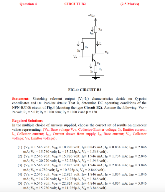
Option 4 is correct
Add Answer to:
please choose one of the answer choices above.
Must show all work, thank you
Question 4...
Electronics1. It's a multiple choices question. use the formula sheet if needed (the last picture). Question...
 Electronics1. It's a multiple choices question. use the formula
sheet if needed (the last picture).
Question 4 CIRCUIT B2 (2.5 Marks) +Voc R ler Vic RS IB Vc V. RE FIG.4: CIRCUIT B2 Statement: Sketching relevant output (VIC) characteristics decide on Q-point coordinates and DC load-line details: That is, determine DC operating conditions of the NPN-BJT/Si circuit of Fig. 4 (denoting the type Circuit B2). Assume the following: Vor = 24 volt; Rc = 5.0 k; Re = 1000 ohm:...
Electronics1. It's a multiple choices question. use the formula
sheet if needed (the last picture).
Question 4 CIRCUIT B2 (2.5 Marks) +Voc R ler Vic RS IB Vc V. RE FIG.4: CIRCUIT B2 Statement: Sketching relevant output (VIC) characteristics decide on Q-point coordinates and DC load-line details: That is, determine DC operating conditions of the NPN-BJT/Si circuit of Fig. 4 (denoting the type Circuit B2). Assume the following: Vor = 24 volt; Rc = 5.0 k; Re = 1000 ohm:...
please choose one of the answer choices above. Must show all work, thank you Question 2...
 please choose one of the answer choices above.
Must show all work, thank you
Question 2 CIRCUIT A2 (2.5 Marks) + Ver Rc Ic с IR Fig. 2: CIRCUIT A.2 Statement: Sketching relevant output (Vc-Ic) characteristics decide on Q-point coordinates and DC load-line details: That is, determine DC operating conditions of the NPN-BJT/Si circuit of Fig.2 (denoting the type Circuit A2). Assume the following: Vcc= 24 volt; Rc = 5.0 k; RB = 1500 k and B = 125. Required...
please choose one of the answer choices above.
Must show all work, thank you
Question 2 CIRCUIT A2 (2.5 Marks) + Ver Rc Ic с IR Fig. 2: CIRCUIT A.2 Statement: Sketching relevant output (Vc-Ic) characteristics decide on Q-point coordinates and DC load-line details: That is, determine DC operating conditions of the NPN-BJT/Si circuit of Fig.2 (denoting the type Circuit A2). Assume the following: Vcc= 24 volt; Rc = 5.0 k; RB = 1500 k and B = 125. Required...
please choose one of the answer choices above. Must show all work, thank you Question 3...
 please choose one of the answer choices above.
Must show all work, thank you
Question 3 CIRCUIT B1 (2.5 Marks) + Vcc Rc IRC > IC RB Ів + VCE IE FIG. 3: CIRCUIT B1 Statement: Sketching relevant output (Vc-Ic) characteristics decide on Q-point coordinates and DC load-line details: That is, determine DC operating conditions of the NPN-BJT/Si circuit of Fig.3 (denoting the type Circuit B1). Assume the following: Vcc= 20 volt; Rc = 2.5 k; RB = 350 k...
please choose one of the answer choices above.
Must show all work, thank you
Question 3 CIRCUIT B1 (2.5 Marks) + Vcc Rc IRC > IC RB Ів + VCE IE FIG. 3: CIRCUIT B1 Statement: Sketching relevant output (Vc-Ic) characteristics decide on Q-point coordinates and DC load-line details: That is, determine DC operating conditions of the NPN-BJT/Si circuit of Fig.3 (denoting the type Circuit B1). Assume the following: Vcc= 20 volt; Rc = 2.5 k; RB = 350 k...
please choose one of the answer choices above. Must show all work, thank you Question 1...
 please choose one of the answer choices above.
Must show all work, thank you
Question 1 CIRCUIT A.1 (2.5 Marks) + Vcc RB IB Rc Vc VB Fig. 1: CIRCUIT A.1 Statement: Sketching relevant output (Vc-Ic) characteristics decide on Q-point coordinates and DC load-line details: That is, determine DC operating conditions of the NPN-BJT/Si circuit of Fig.1 (denoting the type Circuit A1). Assume the following: Vcc= 12 volt; Rc = 3.6 k; RB = 500 k and a = 0.9....
please choose one of the answer choices above.
Must show all work, thank you
Question 1 CIRCUIT A.1 (2.5 Marks) + Vcc RB IB Rc Vc VB Fig. 1: CIRCUIT A.1 Statement: Sketching relevant output (Vc-Ic) characteristics decide on Q-point coordinates and DC load-line details: That is, determine DC operating conditions of the NPN-BJT/Si circuit of Fig.1 (denoting the type Circuit A1). Assume the following: Vcc= 12 volt; Rc = 3.6 k; RB = 500 k and a = 0.9....
please choose one of the answer choices above. Must show all work, thank you! Question 8...
 please choose one of the answer choices above.
Must show all work, thank you!
Question 8 CIRCUIT D.2 (2.5 Marks) Statement: Sketching relevant output (Vc-Ic) characteristics decide on Q-point coordinates and DC load-line details: That is, determine DC operating conditions of the NPN-BJT/Si circuit of Fig.8 (denoting the type Circuit D2). Assume the following: Vcc= 10 volt; VE = 1.8 volt; Rc = 2.0 k; RB2 = 25 k and a = 0.98958. +Vcc Rc IRC RB1 INIC 11 IB...
please choose one of the answer choices above.
Must show all work, thank you!
Question 8 CIRCUIT D.2 (2.5 Marks) Statement: Sketching relevant output (Vc-Ic) characteristics decide on Q-point coordinates and DC load-line details: That is, determine DC operating conditions of the NPN-BJT/Si circuit of Fig.8 (denoting the type Circuit D2). Assume the following: Vcc= 10 volt; VE = 1.8 volt; Rc = 2.0 k; RB2 = 25 k and a = 0.98958. +Vcc Rc IRC RB1 INIC 11 IB...
please choose one of the answer choices above. Must show all work, thank you Question 6...
 please choose one of the answer choices above.
Must show all work, thank you
Question 6 CIRCUIT C2 (2.5 Marks) Statement: Sketching relevant output (Vc-Ic) characteristics decide on Q-point coordinates and DC load-line details: That is, determine DC operating conditions of the NPN-BJT/Si circuit of Fig.6 (denoting the type Circuit C2). Assume the following: Vcc= 30 volt; Rc = 2.0 k; Roi = 15 k; RB2 = 7.5 k; ; RE = 2.0 k; VE = 9.3 volt; and, a=0.98684...
please choose one of the answer choices above.
Must show all work, thank you
Question 6 CIRCUIT C2 (2.5 Marks) Statement: Sketching relevant output (Vc-Ic) characteristics decide on Q-point coordinates and DC load-line details: That is, determine DC operating conditions of the NPN-BJT/Si circuit of Fig.6 (denoting the type Circuit C2). Assume the following: Vcc= 30 volt; Rc = 2.0 k; Roi = 15 k; RB2 = 7.5 k; ; RE = 2.0 k; VE = 9.3 volt; and, a=0.98684...
please choose one of the answer choices above. Must show all work, thank you Question 5...
 please choose one of the answer choices above.
Must show all work, thank you
Question 5 CIRCUIT C1 (2.5 Marks) Statement: Sketching relevant output (Vc-Ic) characteristics decide on Q-point coordinates and DC load-line details: That is, determine DC operating conditions of the NPN-BJT/Si circuit of Fig.5 (denoting the type Circuit C1). Assume the following: Vcc= 18 volt; Rc = 1.5 k; RB1 = 75 k; RB2 = 3.6 k; V CESat = 1 volt; and a = 0.99338. +Vcc VIC...
please choose one of the answer choices above.
Must show all work, thank you
Question 5 CIRCUIT C1 (2.5 Marks) Statement: Sketching relevant output (Vc-Ic) characteristics decide on Q-point coordinates and DC load-line details: That is, determine DC operating conditions of the NPN-BJT/Si circuit of Fig.5 (denoting the type Circuit C1). Assume the following: Vcc= 18 volt; Rc = 1.5 k; RB1 = 75 k; RB2 = 3.6 k; V CESat = 1 volt; and a = 0.99338. +Vcc VIC...
please choose one of the answer choices above. Must show all work, thank you Question 7...
 please choose one of the answer choices above.
Must show all work, thank you
Question 7 CIRCUIT D1 (2.5 Marks) Statement: Sketching relevant output (Vc-Ic) characteristics decide on Q-point coordinates and DC load-line details: That is, determine DC operating conditions of the NPN-BJT/Si circuit of Fig. 7 (denoting the type Circuit C2). Assume the following: Vcc= 18 volt; VBE = 0.7; Rc = 1.5 k; RB2 = 33 k; Vc = 9.5 volt; Irc = 9.5 and, B = 100...
please choose one of the answer choices above.
Must show all work, thank you
Question 7 CIRCUIT D1 (2.5 Marks) Statement: Sketching relevant output (Vc-Ic) characteristics decide on Q-point coordinates and DC load-line details: That is, determine DC operating conditions of the NPN-BJT/Si circuit of Fig. 7 (denoting the type Circuit C2). Assume the following: Vcc= 18 volt; VBE = 0.7; Rc = 1.5 k; RB2 = 33 k; Vc = 9.5 volt; Irc = 9.5 and, B = 100...
Electronics1. It's a multiple choices question. use the formula sheet if needed (the last picture). Question...
 Electronics1. It's a multiple choices question. use the formula
sheet if needed (the last picture).
Question 3 CIRCUIT B1 (2.5 Marks) + VC Rc IRC < + RB IC IB V ce → IE FIG. 3: CIRCUIT B1 Statement: Sketching relevant output (V-Ic) characteristics decide on Q-point coordinates and DC load-line details: That is, determine DC operating conditions of the NPN-BJT/Si circuit of Fig.3 (denoting the type Circuit B1). Assume the following: Vcc= 20 volt; Rc = 2.5 k; RB...
Electronics1. It's a multiple choices question. use the formula
sheet if needed (the last picture).
Question 3 CIRCUIT B1 (2.5 Marks) + VC Rc IRC < + RB IC IB V ce → IE FIG. 3: CIRCUIT B1 Statement: Sketching relevant output (V-Ic) characteristics decide on Q-point coordinates and DC load-line details: That is, determine DC operating conditions of the NPN-BJT/Si circuit of Fig.3 (denoting the type Circuit B1). Assume the following: Vcc= 20 volt; Rc = 2.5 k; RB...
Electronics1. It's a multiple choices question. use the formula sheet if needed (the last picture). Question...
 Electronics1. It's a multiple choices question. use the formula
sheet if needed (the last picture).
Question 2 CIRCUIT A2 (2.5 Marks) non dahil ki VC R. Fig. 2: CIRCUIT A.2 Statement: Sketching relevant output (V-IC) characteristics decide on Q-point coordinates and DC load-line details: That is, determine DC operating conditions of the NPN-BJT/Si circuit of Fig.2 (denoting the type Circuit A2). Assume the following: Voc - 24 volt; Rc = 5.0 k; Rs = 1500k and B = 125. Required...
Electronics1. It's a multiple choices question. use the formula
sheet if needed (the last picture).
Question 2 CIRCUIT A2 (2.5 Marks) non dahil ki VC R. Fig. 2: CIRCUIT A.2 Statement: Sketching relevant output (V-IC) characteristics decide on Q-point coordinates and DC load-line details: That is, determine DC operating conditions of the NPN-BJT/Si circuit of Fig.2 (denoting the type Circuit A2). Assume the following: Voc - 24 volt; Rc = 5.0 k; Rs = 1500k and B = 125. Required...
 Electronics1. It's a multiple choices question. use the formula
sheet if needed (the last picture).
Question 4 CIRCUIT B2 (2.5 Marks) +Voc R ler Vic RS IB Vc V. RE FIG.4: CIRCUIT B2 Statement: Sketching relevant output (VIC) characteristics decide on Q-point coordinates and DC load-line details: That is, determine DC operating conditions of the NPN-BJT/Si circuit of Fig. 4 (denoting the type Circuit B2). Assume the following: Vor = 24 volt; Rc = 5.0 k; Re = 1000 ohm:...
Electronics1. It's a multiple choices question. use the formula
sheet if needed (the last picture).
Question 4 CIRCUIT B2 (2.5 Marks) +Voc R ler Vic RS IB Vc V. RE FIG.4: CIRCUIT B2 Statement: Sketching relevant output (VIC) characteristics decide on Q-point coordinates and DC load-line details: That is, determine DC operating conditions of the NPN-BJT/Si circuit of Fig. 4 (denoting the type Circuit B2). Assume the following: Vor = 24 volt; Rc = 5.0 k; Re = 1000 ohm:...
 please choose one of the answer choices above.
Must show all work, thank you
Question 2 CIRCUIT A2 (2.5 Marks) + Ver Rc Ic с IR Fig. 2: CIRCUIT A.2 Statement: Sketching relevant output (Vc-Ic) characteristics decide on Q-point coordinates and DC load-line details: That is, determine DC operating conditions of the NPN-BJT/Si circuit of Fig.2 (denoting the type Circuit A2). Assume the following: Vcc= 24 volt; Rc = 5.0 k; RB = 1500 k and B = 125. Required...
please choose one of the answer choices above.
Must show all work, thank you
Question 2 CIRCUIT A2 (2.5 Marks) + Ver Rc Ic с IR Fig. 2: CIRCUIT A.2 Statement: Sketching relevant output (Vc-Ic) characteristics decide on Q-point coordinates and DC load-line details: That is, determine DC operating conditions of the NPN-BJT/Si circuit of Fig.2 (denoting the type Circuit A2). Assume the following: Vcc= 24 volt; Rc = 5.0 k; RB = 1500 k and B = 125. Required...
 please choose one of the answer choices above.
Must show all work, thank you
Question 3 CIRCUIT B1 (2.5 Marks) + Vcc Rc IRC > IC RB Ів + VCE IE FIG. 3: CIRCUIT B1 Statement: Sketching relevant output (Vc-Ic) characteristics decide on Q-point coordinates and DC load-line details: That is, determine DC operating conditions of the NPN-BJT/Si circuit of Fig.3 (denoting the type Circuit B1). Assume the following: Vcc= 20 volt; Rc = 2.5 k; RB = 350 k...
please choose one of the answer choices above.
Must show all work, thank you
Question 3 CIRCUIT B1 (2.5 Marks) + Vcc Rc IRC > IC RB Ів + VCE IE FIG. 3: CIRCUIT B1 Statement: Sketching relevant output (Vc-Ic) characteristics decide on Q-point coordinates and DC load-line details: That is, determine DC operating conditions of the NPN-BJT/Si circuit of Fig.3 (denoting the type Circuit B1). Assume the following: Vcc= 20 volt; Rc = 2.5 k; RB = 350 k...
 please choose one of the answer choices above.
Must show all work, thank you
Question 1 CIRCUIT A.1 (2.5 Marks) + Vcc RB IB Rc Vc VB Fig. 1: CIRCUIT A.1 Statement: Sketching relevant output (Vc-Ic) characteristics decide on Q-point coordinates and DC load-line details: That is, determine DC operating conditions of the NPN-BJT/Si circuit of Fig.1 (denoting the type Circuit A1). Assume the following: Vcc= 12 volt; Rc = 3.6 k; RB = 500 k and a = 0.9....
please choose one of the answer choices above.
Must show all work, thank you
Question 1 CIRCUIT A.1 (2.5 Marks) + Vcc RB IB Rc Vc VB Fig. 1: CIRCUIT A.1 Statement: Sketching relevant output (Vc-Ic) characteristics decide on Q-point coordinates and DC load-line details: That is, determine DC operating conditions of the NPN-BJT/Si circuit of Fig.1 (denoting the type Circuit A1). Assume the following: Vcc= 12 volt; Rc = 3.6 k; RB = 500 k and a = 0.9....
 please choose one of the answer choices above.
Must show all work, thank you!
Question 8 CIRCUIT D.2 (2.5 Marks) Statement: Sketching relevant output (Vc-Ic) characteristics decide on Q-point coordinates and DC load-line details: That is, determine DC operating conditions of the NPN-BJT/Si circuit of Fig.8 (denoting the type Circuit D2). Assume the following: Vcc= 10 volt; VE = 1.8 volt; Rc = 2.0 k; RB2 = 25 k and a = 0.98958. +Vcc Rc IRC RB1 INIC 11 IB...
please choose one of the answer choices above.
Must show all work, thank you!
Question 8 CIRCUIT D.2 (2.5 Marks) Statement: Sketching relevant output (Vc-Ic) characteristics decide on Q-point coordinates and DC load-line details: That is, determine DC operating conditions of the NPN-BJT/Si circuit of Fig.8 (denoting the type Circuit D2). Assume the following: Vcc= 10 volt; VE = 1.8 volt; Rc = 2.0 k; RB2 = 25 k and a = 0.98958. +Vcc Rc IRC RB1 INIC 11 IB...
 please choose one of the answer choices above.
Must show all work, thank you
Question 6 CIRCUIT C2 (2.5 Marks) Statement: Sketching relevant output (Vc-Ic) characteristics decide on Q-point coordinates and DC load-line details: That is, determine DC operating conditions of the NPN-BJT/Si circuit of Fig.6 (denoting the type Circuit C2). Assume the following: Vcc= 30 volt; Rc = 2.0 k; Roi = 15 k; RB2 = 7.5 k; ; RE = 2.0 k; VE = 9.3 volt; and, a=0.98684...
please choose one of the answer choices above.
Must show all work, thank you
Question 6 CIRCUIT C2 (2.5 Marks) Statement: Sketching relevant output (Vc-Ic) characteristics decide on Q-point coordinates and DC load-line details: That is, determine DC operating conditions of the NPN-BJT/Si circuit of Fig.6 (denoting the type Circuit C2). Assume the following: Vcc= 30 volt; Rc = 2.0 k; Roi = 15 k; RB2 = 7.5 k; ; RE = 2.0 k; VE = 9.3 volt; and, a=0.98684...
 please choose one of the answer choices above.
Must show all work, thank you
Question 5 CIRCUIT C1 (2.5 Marks) Statement: Sketching relevant output (Vc-Ic) characteristics decide on Q-point coordinates and DC load-line details: That is, determine DC operating conditions of the NPN-BJT/Si circuit of Fig.5 (denoting the type Circuit C1). Assume the following: Vcc= 18 volt; Rc = 1.5 k; RB1 = 75 k; RB2 = 3.6 k; V CESat = 1 volt; and a = 0.99338. +Vcc VIC...
please choose one of the answer choices above.
Must show all work, thank you
Question 5 CIRCUIT C1 (2.5 Marks) Statement: Sketching relevant output (Vc-Ic) characteristics decide on Q-point coordinates and DC load-line details: That is, determine DC operating conditions of the NPN-BJT/Si circuit of Fig.5 (denoting the type Circuit C1). Assume the following: Vcc= 18 volt; Rc = 1.5 k; RB1 = 75 k; RB2 = 3.6 k; V CESat = 1 volt; and a = 0.99338. +Vcc VIC...
 please choose one of the answer choices above.
Must show all work, thank you
Question 7 CIRCUIT D1 (2.5 Marks) Statement: Sketching relevant output (Vc-Ic) characteristics decide on Q-point coordinates and DC load-line details: That is, determine DC operating conditions of the NPN-BJT/Si circuit of Fig. 7 (denoting the type Circuit C2). Assume the following: Vcc= 18 volt; VBE = 0.7; Rc = 1.5 k; RB2 = 33 k; Vc = 9.5 volt; Irc = 9.5 and, B = 100...
please choose one of the answer choices above.
Must show all work, thank you
Question 7 CIRCUIT D1 (2.5 Marks) Statement: Sketching relevant output (Vc-Ic) characteristics decide on Q-point coordinates and DC load-line details: That is, determine DC operating conditions of the NPN-BJT/Si circuit of Fig. 7 (denoting the type Circuit C2). Assume the following: Vcc= 18 volt; VBE = 0.7; Rc = 1.5 k; RB2 = 33 k; Vc = 9.5 volt; Irc = 9.5 and, B = 100...
 Electronics1. It's a multiple choices question. use the formula
sheet if needed (the last picture).
Question 3 CIRCUIT B1 (2.5 Marks) + VC Rc IRC < + RB IC IB V ce → IE FIG. 3: CIRCUIT B1 Statement: Sketching relevant output (V-Ic) characteristics decide on Q-point coordinates and DC load-line details: That is, determine DC operating conditions of the NPN-BJT/Si circuit of Fig.3 (denoting the type Circuit B1). Assume the following: Vcc= 20 volt; Rc = 2.5 k; RB...
Electronics1. It's a multiple choices question. use the formula
sheet if needed (the last picture).
Question 3 CIRCUIT B1 (2.5 Marks) + VC Rc IRC < + RB IC IB V ce → IE FIG. 3: CIRCUIT B1 Statement: Sketching relevant output (V-Ic) characteristics decide on Q-point coordinates and DC load-line details: That is, determine DC operating conditions of the NPN-BJT/Si circuit of Fig.3 (denoting the type Circuit B1). Assume the following: Vcc= 20 volt; Rc = 2.5 k; RB...
 Electronics1. It's a multiple choices question. use the formula
sheet if needed (the last picture).
Question 2 CIRCUIT A2 (2.5 Marks) non dahil ki VC R. Fig. 2: CIRCUIT A.2 Statement: Sketching relevant output (V-IC) characteristics decide on Q-point coordinates and DC load-line details: That is, determine DC operating conditions of the NPN-BJT/Si circuit of Fig.2 (denoting the type Circuit A2). Assume the following: Voc - 24 volt; Rc = 5.0 k; Rs = 1500k and B = 125. Required...
Electronics1. It's a multiple choices question. use the formula
sheet if needed (the last picture).
Question 2 CIRCUIT A2 (2.5 Marks) non dahil ki VC R. Fig. 2: CIRCUIT A.2 Statement: Sketching relevant output (V-IC) characteristics decide on Q-point coordinates and DC load-line details: That is, determine DC operating conditions of the NPN-BJT/Si circuit of Fig.2 (denoting the type Circuit A2). Assume the following: Voc - 24 volt; Rc = 5.0 k; Rs = 1500k and B = 125. Required...
Most questions answered within 3 hours.
-
The free energy change for the following reaction at 25 °C, when
[Sn2+] = 1.17 M...
asked 1 hour ago -
An MNE is this kind of industry when competition in one country
is essentially independent of...
asked 3 hours ago -
. For this set of questions, determine what
proportion of a normal distribution is located betweeneach...
asked 3 hours ago -
A college student is employed as a door-to-door newspaper
salesman. Historical data suggests that the student...
asked 4 hours ago -
MATLAB HW 11 problem using Switch Case and Input commands
Write a script file that calculates...
asked 4 hours ago -
Considering gravitational time dilation, calculate the time that
passes in Earth’s surface while 1 hour passes...
asked 5 hours ago -
Minitab Problem: Take the Lake Hume June rainfall data and find
use the processes outlined in...
asked 6 hours ago -
X Company is trying to decide whether to continue using old
equipment to make Product A...
asked 6 hours ago -
IN PYTHON ONLY !! Program 2: Re-work
program #5 (WeeklyHours) from the previous assignment such that...
asked 6 hours ago -
The average length of time between arrivals at a turnpike
toll-booth is 26 seconds. What is...
asked 8 hours ago -
(a) A piston at 6.1 atm contains a gas that occupies a volume of
3.5 L....
asked 9 hours ago -
Please answer true or false. Words
cannot be changed or added in to make it true...
asked 9 hours ago