

please choose one of the answer choices above.
Must show all work, thank you
Homework Answers
Add Answer to:
please choose one of the answer choices above.
Must show all work, thank you
Question 1...
please choose one of the answer choices above. Must show all work, thank you Question 2...
 please choose one of the answer choices above.
Must show all work, thank you
Question 2 CIRCUIT A2 (2.5 Marks) + Ver Rc Ic с IR Fig. 2: CIRCUIT A.2 Statement: Sketching relevant output (Vc-Ic) characteristics decide on Q-point coordinates and DC load-line details: That is, determine DC operating conditions of the NPN-BJT/Si circuit of Fig.2 (denoting the type Circuit A2). Assume the following: Vcc= 24 volt; Rc = 5.0 k; RB = 1500 k and B = 125. Required...
please choose one of the answer choices above.
Must show all work, thank you
Question 2 CIRCUIT A2 (2.5 Marks) + Ver Rc Ic с IR Fig. 2: CIRCUIT A.2 Statement: Sketching relevant output (Vc-Ic) characteristics decide on Q-point coordinates and DC load-line details: That is, determine DC operating conditions of the NPN-BJT/Si circuit of Fig.2 (denoting the type Circuit A2). Assume the following: Vcc= 24 volt; Rc = 5.0 k; RB = 1500 k and B = 125. Required...
please choose one of the answer choices above. Must show all work, thank you Question 4...
 please choose one of the answer choices above.
Must show all work, thank you
Question 4 CIRCUIT B2 (2.5 Marks) +Vcc Rc IRC Vic RB Ів Vc VB VE RE IE FIG.4: CIRCUIT B2 Statement: Sketching relevant output (Vc-Ic) characteristics decide on Q-point coordinates and DC load-line details: That is, determine DC operating conditions of the NPN-BJT/Si circuit of Fig.4 (denoting the type Circuit B2). Assume the following: Vcc= 24 volt; Rc = 5.0 k; RE = 1000 ohm; RB...
please choose one of the answer choices above.
Must show all work, thank you
Question 4 CIRCUIT B2 (2.5 Marks) +Vcc Rc IRC Vic RB Ів Vc VB VE RE IE FIG.4: CIRCUIT B2 Statement: Sketching relevant output (Vc-Ic) characteristics decide on Q-point coordinates and DC load-line details: That is, determine DC operating conditions of the NPN-BJT/Si circuit of Fig.4 (denoting the type Circuit B2). Assume the following: Vcc= 24 volt; Rc = 5.0 k; RE = 1000 ohm; RB...
please choose one of the answer choices above. Must show all work, thank you Question 3...
 please choose one of the answer choices above.
Must show all work, thank you
Question 3 CIRCUIT B1 (2.5 Marks) + Vcc Rc IRC > IC RB Ів + VCE IE FIG. 3: CIRCUIT B1 Statement: Sketching relevant output (Vc-Ic) characteristics decide on Q-point coordinates and DC load-line details: That is, determine DC operating conditions of the NPN-BJT/Si circuit of Fig.3 (denoting the type Circuit B1). Assume the following: Vcc= 20 volt; Rc = 2.5 k; RB = 350 k...
please choose one of the answer choices above.
Must show all work, thank you
Question 3 CIRCUIT B1 (2.5 Marks) + Vcc Rc IRC > IC RB Ів + VCE IE FIG. 3: CIRCUIT B1 Statement: Sketching relevant output (Vc-Ic) characteristics decide on Q-point coordinates and DC load-line details: That is, determine DC operating conditions of the NPN-BJT/Si circuit of Fig.3 (denoting the type Circuit B1). Assume the following: Vcc= 20 volt; Rc = 2.5 k; RB = 350 k...
please choose one of the answer choices above. Must show all work, thank you! Question 8...
 please choose one of the answer choices above.
Must show all work, thank you!
Question 8 CIRCUIT D.2 (2.5 Marks) Statement: Sketching relevant output (Vc-Ic) characteristics decide on Q-point coordinates and DC load-line details: That is, determine DC operating conditions of the NPN-BJT/Si circuit of Fig.8 (denoting the type Circuit D2). Assume the following: Vcc= 10 volt; VE = 1.8 volt; Rc = 2.0 k; RB2 = 25 k and a = 0.98958. +Vcc Rc IRC RB1 INIC 11 IB...
please choose one of the answer choices above.
Must show all work, thank you!
Question 8 CIRCUIT D.2 (2.5 Marks) Statement: Sketching relevant output (Vc-Ic) characteristics decide on Q-point coordinates and DC load-line details: That is, determine DC operating conditions of the NPN-BJT/Si circuit of Fig.8 (denoting the type Circuit D2). Assume the following: Vcc= 10 volt; VE = 1.8 volt; Rc = 2.0 k; RB2 = 25 k and a = 0.98958. +Vcc Rc IRC RB1 INIC 11 IB...
please choose one of the answer choices above. Must show all work, thank you Question 6...
 please choose one of the answer choices above.
Must show all work, thank you
Question 6 CIRCUIT C2 (2.5 Marks) Statement: Sketching relevant output (Vc-Ic) characteristics decide on Q-point coordinates and DC load-line details: That is, determine DC operating conditions of the NPN-BJT/Si circuit of Fig.6 (denoting the type Circuit C2). Assume the following: Vcc= 30 volt; Rc = 2.0 k; Roi = 15 k; RB2 = 7.5 k; ; RE = 2.0 k; VE = 9.3 volt; and, a=0.98684...
please choose one of the answer choices above.
Must show all work, thank you
Question 6 CIRCUIT C2 (2.5 Marks) Statement: Sketching relevant output (Vc-Ic) characteristics decide on Q-point coordinates and DC load-line details: That is, determine DC operating conditions of the NPN-BJT/Si circuit of Fig.6 (denoting the type Circuit C2). Assume the following: Vcc= 30 volt; Rc = 2.0 k; Roi = 15 k; RB2 = 7.5 k; ; RE = 2.0 k; VE = 9.3 volt; and, a=0.98684...
please choose one of the answer choices above. Must show all work, thank you Question 5...
 please choose one of the answer choices above.
Must show all work, thank you
Question 5 CIRCUIT C1 (2.5 Marks) Statement: Sketching relevant output (Vc-Ic) characteristics decide on Q-point coordinates and DC load-line details: That is, determine DC operating conditions of the NPN-BJT/Si circuit of Fig.5 (denoting the type Circuit C1). Assume the following: Vcc= 18 volt; Rc = 1.5 k; RB1 = 75 k; RB2 = 3.6 k; V CESat = 1 volt; and a = 0.99338. +Vcc VIC...
please choose one of the answer choices above.
Must show all work, thank you
Question 5 CIRCUIT C1 (2.5 Marks) Statement: Sketching relevant output (Vc-Ic) characteristics decide on Q-point coordinates and DC load-line details: That is, determine DC operating conditions of the NPN-BJT/Si circuit of Fig.5 (denoting the type Circuit C1). Assume the following: Vcc= 18 volt; Rc = 1.5 k; RB1 = 75 k; RB2 = 3.6 k; V CESat = 1 volt; and a = 0.99338. +Vcc VIC...
please choose one of the answer choices above. Must show all work, thank you Question 7...
 please choose one of the answer choices above.
Must show all work, thank you
Question 7 CIRCUIT D1 (2.5 Marks) Statement: Sketching relevant output (Vc-Ic) characteristics decide on Q-point coordinates and DC load-line details: That is, determine DC operating conditions of the NPN-BJT/Si circuit of Fig. 7 (denoting the type Circuit C2). Assume the following: Vcc= 18 volt; VBE = 0.7; Rc = 1.5 k; RB2 = 33 k; Vc = 9.5 volt; Irc = 9.5 and, B = 100...
please choose one of the answer choices above.
Must show all work, thank you
Question 7 CIRCUIT D1 (2.5 Marks) Statement: Sketching relevant output (Vc-Ic) characteristics decide on Q-point coordinates and DC load-line details: That is, determine DC operating conditions of the NPN-BJT/Si circuit of Fig. 7 (denoting the type Circuit C2). Assume the following: Vcc= 18 volt; VBE = 0.7; Rc = 1.5 k; RB2 = 33 k; Vc = 9.5 volt; Irc = 9.5 and, B = 100...
Electronics1. It's a multiple choices question. use the formula sheet if needed (the last picture). Question...
 Electronics1. It's a multiple choices question. use the formula
sheet if needed (the last picture).
Question 3 CIRCUIT B1 (2.5 Marks) + VC Rc IRC < + RB IC IB V ce → IE FIG. 3: CIRCUIT B1 Statement: Sketching relevant output (V-Ic) characteristics decide on Q-point coordinates and DC load-line details: That is, determine DC operating conditions of the NPN-BJT/Si circuit of Fig.3 (denoting the type Circuit B1). Assume the following: Vcc= 20 volt; Rc = 2.5 k; RB...
Electronics1. It's a multiple choices question. use the formula
sheet if needed (the last picture).
Question 3 CIRCUIT B1 (2.5 Marks) + VC Rc IRC < + RB IC IB V ce → IE FIG. 3: CIRCUIT B1 Statement: Sketching relevant output (V-Ic) characteristics decide on Q-point coordinates and DC load-line details: That is, determine DC operating conditions of the NPN-BJT/Si circuit of Fig.3 (denoting the type Circuit B1). Assume the following: Vcc= 20 volt; Rc = 2.5 k; RB...
Electronics1. It's a multiple choices question. use the formula sheet if needed (the last picture). Question...
 Electronics1. It's a multiple choices question. use the formula
sheet if needed (the last picture).
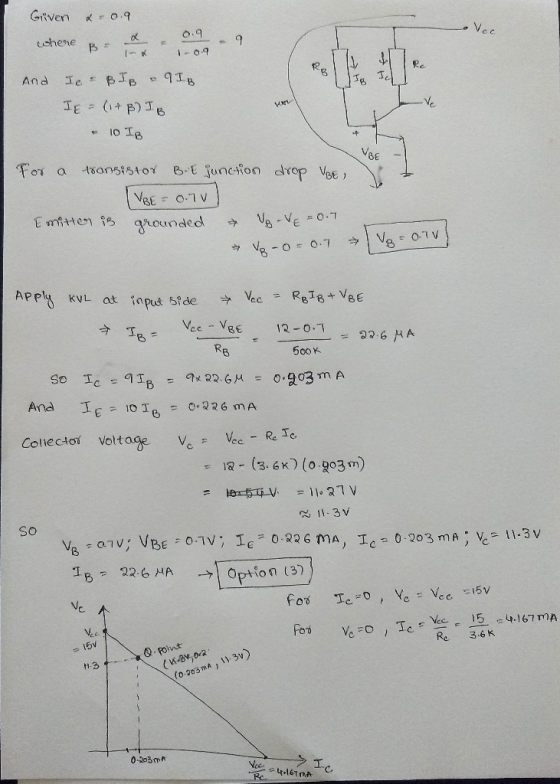
Question 1 CIRCUIT A.1 (2.5 Marks) +Vec R RC clic Vc Fig. 1: CIRCUIT A.1 Statement: Sketching relevant output (V-le) characteristics decide on Q-point coordinates and DC load-line details: That is, determine DC operating conditions of the NPN-BJT/Si circuit of Fig.1 (denoting the type Circuit A1). Assume the following: Voe= 12 volt: Rc = 3.6k; R = 500k and a =0.9. Required Solutions From the...
Electronics1. It's a multiple choices question. use the formula
sheet if needed (the last picture).
Question 1 CIRCUIT A.1 (2.5 Marks) +Vec R RC clic Vc Fig. 1: CIRCUIT A.1 Statement: Sketching relevant output (V-le) characteristics decide on Q-point coordinates and DC load-line details: That is, determine DC operating conditions of the NPN-BJT/Si circuit of Fig.1 (denoting the type Circuit A1). Assume the following: Voe= 12 volt: Rc = 3.6k; R = 500k and a =0.9. Required Solutions From the...
5 نقاط For the circuit shown, If there is an added 1 K. Ohm resistor at...
 5 نقاط For the circuit shown, If there is an added 1 K. Ohm resistor at the emitter terminal connected between Emitter and Ground, then calculate IB, IC, VCE, VB, and VC knowing that Vcc = 12 Volts, RB = 220 K. Ohm, RC = 4 K. Ohm, VBE = 0.7 volts, and Beta of transistor = 50 VCC Fig. 1 Rc im Ic RB ac HE output signal C2 IB + ac VCE input I signal G B +...
 please choose one of the answer choices above.
Must show all work, thank you
Question 2 CIRCUIT A2 (2.5 Marks) + Ver Rc Ic с IR Fig. 2: CIRCUIT A.2 Statement: Sketching relevant output (Vc-Ic) characteristics decide on Q-point coordinates and DC load-line details: That is, determine DC operating conditions of the NPN-BJT/Si circuit of Fig.2 (denoting the type Circuit A2). Assume the following: Vcc= 24 volt; Rc = 5.0 k; RB = 1500 k and B = 125. Required...
please choose one of the answer choices above.
Must show all work, thank you
Question 2 CIRCUIT A2 (2.5 Marks) + Ver Rc Ic с IR Fig. 2: CIRCUIT A.2 Statement: Sketching relevant output (Vc-Ic) characteristics decide on Q-point coordinates and DC load-line details: That is, determine DC operating conditions of the NPN-BJT/Si circuit of Fig.2 (denoting the type Circuit A2). Assume the following: Vcc= 24 volt; Rc = 5.0 k; RB = 1500 k and B = 125. Required...
 please choose one of the answer choices above.
Must show all work, thank you
Question 4 CIRCUIT B2 (2.5 Marks) +Vcc Rc IRC Vic RB Ів Vc VB VE RE IE FIG.4: CIRCUIT B2 Statement: Sketching relevant output (Vc-Ic) characteristics decide on Q-point coordinates and DC load-line details: That is, determine DC operating conditions of the NPN-BJT/Si circuit of Fig.4 (denoting the type Circuit B2). Assume the following: Vcc= 24 volt; Rc = 5.0 k; RE = 1000 ohm; RB...
please choose one of the answer choices above.
Must show all work, thank you
Question 4 CIRCUIT B2 (2.5 Marks) +Vcc Rc IRC Vic RB Ів Vc VB VE RE IE FIG.4: CIRCUIT B2 Statement: Sketching relevant output (Vc-Ic) characteristics decide on Q-point coordinates and DC load-line details: That is, determine DC operating conditions of the NPN-BJT/Si circuit of Fig.4 (denoting the type Circuit B2). Assume the following: Vcc= 24 volt; Rc = 5.0 k; RE = 1000 ohm; RB...
 please choose one of the answer choices above.
Must show all work, thank you
Question 3 CIRCUIT B1 (2.5 Marks) + Vcc Rc IRC > IC RB Ів + VCE IE FIG. 3: CIRCUIT B1 Statement: Sketching relevant output (Vc-Ic) characteristics decide on Q-point coordinates and DC load-line details: That is, determine DC operating conditions of the NPN-BJT/Si circuit of Fig.3 (denoting the type Circuit B1). Assume the following: Vcc= 20 volt; Rc = 2.5 k; RB = 350 k...
please choose one of the answer choices above.
Must show all work, thank you
Question 3 CIRCUIT B1 (2.5 Marks) + Vcc Rc IRC > IC RB Ів + VCE IE FIG. 3: CIRCUIT B1 Statement: Sketching relevant output (Vc-Ic) characteristics decide on Q-point coordinates and DC load-line details: That is, determine DC operating conditions of the NPN-BJT/Si circuit of Fig.3 (denoting the type Circuit B1). Assume the following: Vcc= 20 volt; Rc = 2.5 k; RB = 350 k...
 please choose one of the answer choices above.
Must show all work, thank you!
Question 8 CIRCUIT D.2 (2.5 Marks) Statement: Sketching relevant output (Vc-Ic) characteristics decide on Q-point coordinates and DC load-line details: That is, determine DC operating conditions of the NPN-BJT/Si circuit of Fig.8 (denoting the type Circuit D2). Assume the following: Vcc= 10 volt; VE = 1.8 volt; Rc = 2.0 k; RB2 = 25 k and a = 0.98958. +Vcc Rc IRC RB1 INIC 11 IB...
please choose one of the answer choices above.
Must show all work, thank you!
Question 8 CIRCUIT D.2 (2.5 Marks) Statement: Sketching relevant output (Vc-Ic) characteristics decide on Q-point coordinates and DC load-line details: That is, determine DC operating conditions of the NPN-BJT/Si circuit of Fig.8 (denoting the type Circuit D2). Assume the following: Vcc= 10 volt; VE = 1.8 volt; Rc = 2.0 k; RB2 = 25 k and a = 0.98958. +Vcc Rc IRC RB1 INIC 11 IB...
 please choose one of the answer choices above.
Must show all work, thank you
Question 6 CIRCUIT C2 (2.5 Marks) Statement: Sketching relevant output (Vc-Ic) characteristics decide on Q-point coordinates and DC load-line details: That is, determine DC operating conditions of the NPN-BJT/Si circuit of Fig.6 (denoting the type Circuit C2). Assume the following: Vcc= 30 volt; Rc = 2.0 k; Roi = 15 k; RB2 = 7.5 k; ; RE = 2.0 k; VE = 9.3 volt; and, a=0.98684...
please choose one of the answer choices above.
Must show all work, thank you
Question 6 CIRCUIT C2 (2.5 Marks) Statement: Sketching relevant output (Vc-Ic) characteristics decide on Q-point coordinates and DC load-line details: That is, determine DC operating conditions of the NPN-BJT/Si circuit of Fig.6 (denoting the type Circuit C2). Assume the following: Vcc= 30 volt; Rc = 2.0 k; Roi = 15 k; RB2 = 7.5 k; ; RE = 2.0 k; VE = 9.3 volt; and, a=0.98684...
 please choose one of the answer choices above.
Must show all work, thank you
Question 5 CIRCUIT C1 (2.5 Marks) Statement: Sketching relevant output (Vc-Ic) characteristics decide on Q-point coordinates and DC load-line details: That is, determine DC operating conditions of the NPN-BJT/Si circuit of Fig.5 (denoting the type Circuit C1). Assume the following: Vcc= 18 volt; Rc = 1.5 k; RB1 = 75 k; RB2 = 3.6 k; V CESat = 1 volt; and a = 0.99338. +Vcc VIC...
please choose one of the answer choices above.
Must show all work, thank you
Question 5 CIRCUIT C1 (2.5 Marks) Statement: Sketching relevant output (Vc-Ic) characteristics decide on Q-point coordinates and DC load-line details: That is, determine DC operating conditions of the NPN-BJT/Si circuit of Fig.5 (denoting the type Circuit C1). Assume the following: Vcc= 18 volt; Rc = 1.5 k; RB1 = 75 k; RB2 = 3.6 k; V CESat = 1 volt; and a = 0.99338. +Vcc VIC...
 please choose one of the answer choices above.
Must show all work, thank you
Question 7 CIRCUIT D1 (2.5 Marks) Statement: Sketching relevant output (Vc-Ic) characteristics decide on Q-point coordinates and DC load-line details: That is, determine DC operating conditions of the NPN-BJT/Si circuit of Fig. 7 (denoting the type Circuit C2). Assume the following: Vcc= 18 volt; VBE = 0.7; Rc = 1.5 k; RB2 = 33 k; Vc = 9.5 volt; Irc = 9.5 and, B = 100...
please choose one of the answer choices above.
Must show all work, thank you
Question 7 CIRCUIT D1 (2.5 Marks) Statement: Sketching relevant output (Vc-Ic) characteristics decide on Q-point coordinates and DC load-line details: That is, determine DC operating conditions of the NPN-BJT/Si circuit of Fig. 7 (denoting the type Circuit C2). Assume the following: Vcc= 18 volt; VBE = 0.7; Rc = 1.5 k; RB2 = 33 k; Vc = 9.5 volt; Irc = 9.5 and, B = 100...
 Electronics1. It's a multiple choices question. use the formula
sheet if needed (the last picture).
Question 3 CIRCUIT B1 (2.5 Marks) + VC Rc IRC < + RB IC IB V ce → IE FIG. 3: CIRCUIT B1 Statement: Sketching relevant output (V-Ic) characteristics decide on Q-point coordinates and DC load-line details: That is, determine DC operating conditions of the NPN-BJT/Si circuit of Fig.3 (denoting the type Circuit B1). Assume the following: Vcc= 20 volt; Rc = 2.5 k; RB...
Electronics1. It's a multiple choices question. use the formula
sheet if needed (the last picture).
Question 3 CIRCUIT B1 (2.5 Marks) + VC Rc IRC < + RB IC IB V ce → IE FIG. 3: CIRCUIT B1 Statement: Sketching relevant output (V-Ic) characteristics decide on Q-point coordinates and DC load-line details: That is, determine DC operating conditions of the NPN-BJT/Si circuit of Fig.3 (denoting the type Circuit B1). Assume the following: Vcc= 20 volt; Rc = 2.5 k; RB...
 Electronics1. It's a multiple choices question. use the formula
sheet if needed (the last picture).
Question 1 CIRCUIT A.1 (2.5 Marks) +Vec R RC clic Vc Fig. 1: CIRCUIT A.1 Statement: Sketching relevant output (V-le) characteristics decide on Q-point coordinates and DC load-line details: That is, determine DC operating conditions of the NPN-BJT/Si circuit of Fig.1 (denoting the type Circuit A1). Assume the following: Voe= 12 volt: Rc = 3.6k; R = 500k and a =0.9. Required Solutions From the...
Electronics1. It's a multiple choices question. use the formula
sheet if needed (the last picture).
Question 1 CIRCUIT A.1 (2.5 Marks) +Vec R RC clic Vc Fig. 1: CIRCUIT A.1 Statement: Sketching relevant output (V-le) characteristics decide on Q-point coordinates and DC load-line details: That is, determine DC operating conditions of the NPN-BJT/Si circuit of Fig.1 (denoting the type Circuit A1). Assume the following: Voe= 12 volt: Rc = 3.6k; R = 500k and a =0.9. Required Solutions From the...
 5 نقاط For the circuit shown, If there is an added 1 K. Ohm resistor at the emitter terminal connected between Emitter and Ground, then calculate IB, IC, VCE, VB, and VC knowing that Vcc = 12 Volts, RB = 220 K. Ohm, RC = 4 K. Ohm, VBE = 0.7 volts, and Beta of transistor = 50 VCC Fig. 1 Rc im Ic RB ac HE output signal C2 IB + ac VCE input I signal G B +...
Most questions answered within 3 hours.
-
Starting with benzene, synthesize 1-phenyl-1-butyne.
Show intermediates and reagents.
asked 37 minutes ago -
Create a 32-run crossed array design with six control factors
and two noise factors such that...
asked 1 hour ago -
A 500g sample of sand from source A has the following amounts
retained on each sieve....
asked 1 hour ago -
In
your own words, please explain the essay by John Keynes wrote "The
End of Laissez...
asked 1 hour ago -
How are the matrix and pixels related? Why are smaller
pixels better for diagnostic quality?
asked 1 hour ago -
2. An AC generator has 80 rectangular loops on
its armature. Each loop is 11 cm...
asked 1 hour ago -
Please help me with this question. Consider Aldi’s current and
potential geographic markets (see Exhibit 4...
asked 1 hour ago -
What are the main components of the fermentation process and
give an explanation of each? Include...
asked 2 hours ago -
Explain which types of cells in the body (belonging to which
organs, etc.) are sensitive to...
asked 2 hours ago -
A single cable supports an 703-kg elevator car. What is the
tension in the cable when...
asked 2 hours ago -
among the three different ways to link CSS specifications to an
HTML document (inline CSS, document...
asked 2 hours ago -
(1) Write the net ionic equation for the reaction that occurs
when equal volumes of 0.191...
asked 2 hours ago