please choose one of the answer choices above.
Must show all work, thank you
Homework Answers


Add Answer to:
please choose one of the answer choices above.
Must show all work, thank you
Question 5...
please choose one of the answer choices above. Must show all work, thank you Question 6...
 please choose one of the answer choices above.
Must show all work, thank you
Question 6 CIRCUIT C2 (2.5 Marks) Statement: Sketching relevant output (Vc-Ic) characteristics decide on Q-point coordinates and DC load-line details: That is, determine DC operating conditions of the NPN-BJT/Si circuit of Fig.6 (denoting the type Circuit C2). Assume the following: Vcc= 30 volt; Rc = 2.0 k; Roi = 15 k; RB2 = 7.5 k; ; RE = 2.0 k; VE = 9.3 volt; and, a=0.98684...
please choose one of the answer choices above.
Must show all work, thank you
Question 6 CIRCUIT C2 (2.5 Marks) Statement: Sketching relevant output (Vc-Ic) characteristics decide on Q-point coordinates and DC load-line details: That is, determine DC operating conditions of the NPN-BJT/Si circuit of Fig.6 (denoting the type Circuit C2). Assume the following: Vcc= 30 volt; Rc = 2.0 k; Roi = 15 k; RB2 = 7.5 k; ; RE = 2.0 k; VE = 9.3 volt; and, a=0.98684...
please choose one of the answer choices above. Must show all work, thank you! Question 8...
 please choose one of the answer choices above.
Must show all work, thank you!
Question 8 CIRCUIT D.2 (2.5 Marks) Statement: Sketching relevant output (Vc-Ic) characteristics decide on Q-point coordinates and DC load-line details: That is, determine DC operating conditions of the NPN-BJT/Si circuit of Fig.8 (denoting the type Circuit D2). Assume the following: Vcc= 10 volt; VE = 1.8 volt; Rc = 2.0 k; RB2 = 25 k and a = 0.98958. +Vcc Rc IRC RB1 INIC 11 IB...
please choose one of the answer choices above.
Must show all work, thank you!
Question 8 CIRCUIT D.2 (2.5 Marks) Statement: Sketching relevant output (Vc-Ic) characteristics decide on Q-point coordinates and DC load-line details: That is, determine DC operating conditions of the NPN-BJT/Si circuit of Fig.8 (denoting the type Circuit D2). Assume the following: Vcc= 10 volt; VE = 1.8 volt; Rc = 2.0 k; RB2 = 25 k and a = 0.98958. +Vcc Rc IRC RB1 INIC 11 IB...
please choose one of the answer choices above. Must show all work, thank you Question 7...
 please choose one of the answer choices above.
Must show all work, thank you
Question 7 CIRCUIT D1 (2.5 Marks) Statement: Sketching relevant output (Vc-Ic) characteristics decide on Q-point coordinates and DC load-line details: That is, determine DC operating conditions of the NPN-BJT/Si circuit of Fig. 7 (denoting the type Circuit C2). Assume the following: Vcc= 18 volt; VBE = 0.7; Rc = 1.5 k; RB2 = 33 k; Vc = 9.5 volt; Irc = 9.5 and, B = 100...
please choose one of the answer choices above.
Must show all work, thank you
Question 7 CIRCUIT D1 (2.5 Marks) Statement: Sketching relevant output (Vc-Ic) characteristics decide on Q-point coordinates and DC load-line details: That is, determine DC operating conditions of the NPN-BJT/Si circuit of Fig. 7 (denoting the type Circuit C2). Assume the following: Vcc= 18 volt; VBE = 0.7; Rc = 1.5 k; RB2 = 33 k; Vc = 9.5 volt; Irc = 9.5 and, B = 100...
please choose one of the answer choices above. Must show all work, thank you Question 1...
 please choose one of the answer choices above.
Must show all work, thank you
Question 1 CIRCUIT A.1 (2.5 Marks) + Vcc RB IB Rc Vc VB Fig. 1: CIRCUIT A.1 Statement: Sketching relevant output (Vc-Ic) characteristics decide on Q-point coordinates and DC load-line details: That is, determine DC operating conditions of the NPN-BJT/Si circuit of Fig.1 (denoting the type Circuit A1). Assume the following: Vcc= 12 volt; Rc = 3.6 k; RB = 500 k and a = 0.9....
please choose one of the answer choices above.
Must show all work, thank you
Question 1 CIRCUIT A.1 (2.5 Marks) + Vcc RB IB Rc Vc VB Fig. 1: CIRCUIT A.1 Statement: Sketching relevant output (Vc-Ic) characteristics decide on Q-point coordinates and DC load-line details: That is, determine DC operating conditions of the NPN-BJT/Si circuit of Fig.1 (denoting the type Circuit A1). Assume the following: Vcc= 12 volt; Rc = 3.6 k; RB = 500 k and a = 0.9....
please choose one of the answer choices above. Must show all work, thank you Question 2...
 please choose one of the answer choices above.
Must show all work, thank you
Question 2 CIRCUIT A2 (2.5 Marks) + Ver Rc Ic с IR Fig. 2: CIRCUIT A.2 Statement: Sketching relevant output (Vc-Ic) characteristics decide on Q-point coordinates and DC load-line details: That is, determine DC operating conditions of the NPN-BJT/Si circuit of Fig.2 (denoting the type Circuit A2). Assume the following: Vcc= 24 volt; Rc = 5.0 k; RB = 1500 k and B = 125. Required...
please choose one of the answer choices above.
Must show all work, thank you
Question 2 CIRCUIT A2 (2.5 Marks) + Ver Rc Ic с IR Fig. 2: CIRCUIT A.2 Statement: Sketching relevant output (Vc-Ic) characteristics decide on Q-point coordinates and DC load-line details: That is, determine DC operating conditions of the NPN-BJT/Si circuit of Fig.2 (denoting the type Circuit A2). Assume the following: Vcc= 24 volt; Rc = 5.0 k; RB = 1500 k and B = 125. Required...
please choose one of the answer choices above. Must show all work, thank you Question 4...
 please choose one of the answer choices above.
Must show all work, thank you
Question 4 CIRCUIT B2 (2.5 Marks) +Vcc Rc IRC Vic RB Ів Vc VB VE RE IE FIG.4: CIRCUIT B2 Statement: Sketching relevant output (Vc-Ic) characteristics decide on Q-point coordinates and DC load-line details: That is, determine DC operating conditions of the NPN-BJT/Si circuit of Fig.4 (denoting the type Circuit B2). Assume the following: Vcc= 24 volt; Rc = 5.0 k; RE = 1000 ohm; RB...
please choose one of the answer choices above.
Must show all work, thank you
Question 4 CIRCUIT B2 (2.5 Marks) +Vcc Rc IRC Vic RB Ів Vc VB VE RE IE FIG.4: CIRCUIT B2 Statement: Sketching relevant output (Vc-Ic) characteristics decide on Q-point coordinates and DC load-line details: That is, determine DC operating conditions of the NPN-BJT/Si circuit of Fig.4 (denoting the type Circuit B2). Assume the following: Vcc= 24 volt; Rc = 5.0 k; RE = 1000 ohm; RB...
please choose one of the answer choices above. Must show all work, thank you Question 3...
 please choose one of the answer choices above.
Must show all work, thank you
Question 3 CIRCUIT B1 (2.5 Marks) + Vcc Rc IRC > IC RB Ів + VCE IE FIG. 3: CIRCUIT B1 Statement: Sketching relevant output (Vc-Ic) characteristics decide on Q-point coordinates and DC load-line details: That is, determine DC operating conditions of the NPN-BJT/Si circuit of Fig.3 (denoting the type Circuit B1). Assume the following: Vcc= 20 volt; Rc = 2.5 k; RB = 350 k...
please choose one of the answer choices above.
Must show all work, thank you
Question 3 CIRCUIT B1 (2.5 Marks) + Vcc Rc IRC > IC RB Ів + VCE IE FIG. 3: CIRCUIT B1 Statement: Sketching relevant output (Vc-Ic) characteristics decide on Q-point coordinates and DC load-line details: That is, determine DC operating conditions of the NPN-BJT/Si circuit of Fig.3 (denoting the type Circuit B1). Assume the following: Vcc= 20 volt; Rc = 2.5 k; RB = 350 k...
Electronics1. It's a multiple choices question. use the formula sheet if needed (the last picture). Question...
 Electronics1. It's a multiple choices question. use the formula
sheet if needed (the last picture).
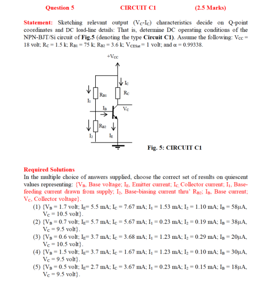
Question 5 CIRCUIT C1 (2.5 Marks) Statement: Sketching relevant output (Vc-le) characteristics decide on Q-point coordinates and DC load-line details: That is, determine DC operating conditions of the NPN-BJT/Si circuit of Fig.5 (denoting the type Circuit C1). Assume the following: Voc= 18 volt; Re = 1.5 k; Rs1 = 75 k; Re2 = 3.6 k; VESu = 1 volt; and a = 0.99338. +Vec Vic...
Electronics1. It's a multiple choices question. use the formula
sheet if needed (the last picture).
Question 5 CIRCUIT C1 (2.5 Marks) Statement: Sketching relevant output (Vc-le) characteristics decide on Q-point coordinates and DC load-line details: That is, determine DC operating conditions of the NPN-BJT/Si circuit of Fig.5 (denoting the type Circuit C1). Assume the following: Voc= 18 volt; Re = 1.5 k; Rs1 = 75 k; Re2 = 3.6 k; VESu = 1 volt; and a = 0.99338. +Vec Vic...
choose one of the multiple choice answers above. please show all work Question: 10 CIRCUIT Y...
 choose one of the multiple choice answers above.
please show all work
Question: 10 CIRCUIT Y FIG.10 (5 Marks) Statement: Consider the RC-coupled amplifier circuit illustrated in Fig. 10 (CIRCUIT Y). Sketching relevant output (Vc-Ic) characteristics, decide Q-point coordinates and DC load-line details (of the NPN-BJT/Si circuit of Fig. 10 of Circuit Y). Further, establish an appropriate AC-load line and decide the maximum swing of the output voltage across Rload with respect to the Q-point. Assume the input signal at...
choose one of the multiple choice answers above.
please show all work
Question: 10 CIRCUIT Y FIG.10 (5 Marks) Statement: Consider the RC-coupled amplifier circuit illustrated in Fig. 10 (CIRCUIT Y). Sketching relevant output (Vc-Ic) characteristics, decide Q-point coordinates and DC load-line details (of the NPN-BJT/Si circuit of Fig. 10 of Circuit Y). Further, establish an appropriate AC-load line and decide the maximum swing of the output voltage across Rload with respect to the Q-point. Assume the input signal at...
please pick one of the multiple choice options above. show all work, thank you Question 9...
 please pick one of the multiple choice options above.
show all work, thank you
Question 9 CIRCUIT X/FIG.9 (5 Marks) Statement: Consider the RC-coupled amplifier circuit illustrated in Fig. 9 (CIRCUIT X). Sketching relevant output (Vc-Ic) characteristics that decide Q-point coordinates and DC load-line details (of the NPN-BJT/Si circuit of Fig. 9 of Circuit X) Further, establish an appropriate AC-load line and decide the maximum swing of the output voltage across Rload with respect to the Q-point. Assume the input...
please pick one of the multiple choice options above.
show all work, thank you
Question 9 CIRCUIT X/FIG.9 (5 Marks) Statement: Consider the RC-coupled amplifier circuit illustrated in Fig. 9 (CIRCUIT X). Sketching relevant output (Vc-Ic) characteristics that decide Q-point coordinates and DC load-line details (of the NPN-BJT/Si circuit of Fig. 9 of Circuit X) Further, establish an appropriate AC-load line and decide the maximum swing of the output voltage across Rload with respect to the Q-point. Assume the input...
 please choose one of the answer choices above.
Must show all work, thank you
Question 6 CIRCUIT C2 (2.5 Marks) Statement: Sketching relevant output (Vc-Ic) characteristics decide on Q-point coordinates and DC load-line details: That is, determine DC operating conditions of the NPN-BJT/Si circuit of Fig.6 (denoting the type Circuit C2). Assume the following: Vcc= 30 volt; Rc = 2.0 k; Roi = 15 k; RB2 = 7.5 k; ; RE = 2.0 k; VE = 9.3 volt; and, a=0.98684...
please choose one of the answer choices above.
Must show all work, thank you
Question 6 CIRCUIT C2 (2.5 Marks) Statement: Sketching relevant output (Vc-Ic) characteristics decide on Q-point coordinates and DC load-line details: That is, determine DC operating conditions of the NPN-BJT/Si circuit of Fig.6 (denoting the type Circuit C2). Assume the following: Vcc= 30 volt; Rc = 2.0 k; Roi = 15 k; RB2 = 7.5 k; ; RE = 2.0 k; VE = 9.3 volt; and, a=0.98684...
 please choose one of the answer choices above.
Must show all work, thank you!
Question 8 CIRCUIT D.2 (2.5 Marks) Statement: Sketching relevant output (Vc-Ic) characteristics decide on Q-point coordinates and DC load-line details: That is, determine DC operating conditions of the NPN-BJT/Si circuit of Fig.8 (denoting the type Circuit D2). Assume the following: Vcc= 10 volt; VE = 1.8 volt; Rc = 2.0 k; RB2 = 25 k and a = 0.98958. +Vcc Rc IRC RB1 INIC 11 IB...
please choose one of the answer choices above.
Must show all work, thank you!
Question 8 CIRCUIT D.2 (2.5 Marks) Statement: Sketching relevant output (Vc-Ic) characteristics decide on Q-point coordinates and DC load-line details: That is, determine DC operating conditions of the NPN-BJT/Si circuit of Fig.8 (denoting the type Circuit D2). Assume the following: Vcc= 10 volt; VE = 1.8 volt; Rc = 2.0 k; RB2 = 25 k and a = 0.98958. +Vcc Rc IRC RB1 INIC 11 IB...
 please choose one of the answer choices above.
Must show all work, thank you
Question 7 CIRCUIT D1 (2.5 Marks) Statement: Sketching relevant output (Vc-Ic) characteristics decide on Q-point coordinates and DC load-line details: That is, determine DC operating conditions of the NPN-BJT/Si circuit of Fig. 7 (denoting the type Circuit C2). Assume the following: Vcc= 18 volt; VBE = 0.7; Rc = 1.5 k; RB2 = 33 k; Vc = 9.5 volt; Irc = 9.5 and, B = 100...
please choose one of the answer choices above.
Must show all work, thank you
Question 7 CIRCUIT D1 (2.5 Marks) Statement: Sketching relevant output (Vc-Ic) characteristics decide on Q-point coordinates and DC load-line details: That is, determine DC operating conditions of the NPN-BJT/Si circuit of Fig. 7 (denoting the type Circuit C2). Assume the following: Vcc= 18 volt; VBE = 0.7; Rc = 1.5 k; RB2 = 33 k; Vc = 9.5 volt; Irc = 9.5 and, B = 100...
 please choose one of the answer choices above.
Must show all work, thank you
Question 1 CIRCUIT A.1 (2.5 Marks) + Vcc RB IB Rc Vc VB Fig. 1: CIRCUIT A.1 Statement: Sketching relevant output (Vc-Ic) characteristics decide on Q-point coordinates and DC load-line details: That is, determine DC operating conditions of the NPN-BJT/Si circuit of Fig.1 (denoting the type Circuit A1). Assume the following: Vcc= 12 volt; Rc = 3.6 k; RB = 500 k and a = 0.9....
please choose one of the answer choices above.
Must show all work, thank you
Question 1 CIRCUIT A.1 (2.5 Marks) + Vcc RB IB Rc Vc VB Fig. 1: CIRCUIT A.1 Statement: Sketching relevant output (Vc-Ic) characteristics decide on Q-point coordinates and DC load-line details: That is, determine DC operating conditions of the NPN-BJT/Si circuit of Fig.1 (denoting the type Circuit A1). Assume the following: Vcc= 12 volt; Rc = 3.6 k; RB = 500 k and a = 0.9....
 please choose one of the answer choices above.
Must show all work, thank you
Question 2 CIRCUIT A2 (2.5 Marks) + Ver Rc Ic с IR Fig. 2: CIRCUIT A.2 Statement: Sketching relevant output (Vc-Ic) characteristics decide on Q-point coordinates and DC load-line details: That is, determine DC operating conditions of the NPN-BJT/Si circuit of Fig.2 (denoting the type Circuit A2). Assume the following: Vcc= 24 volt; Rc = 5.0 k; RB = 1500 k and B = 125. Required...
please choose one of the answer choices above.
Must show all work, thank you
Question 2 CIRCUIT A2 (2.5 Marks) + Ver Rc Ic с IR Fig. 2: CIRCUIT A.2 Statement: Sketching relevant output (Vc-Ic) characteristics decide on Q-point coordinates and DC load-line details: That is, determine DC operating conditions of the NPN-BJT/Si circuit of Fig.2 (denoting the type Circuit A2). Assume the following: Vcc= 24 volt; Rc = 5.0 k; RB = 1500 k and B = 125. Required...
 please choose one of the answer choices above.
Must show all work, thank you
Question 4 CIRCUIT B2 (2.5 Marks) +Vcc Rc IRC Vic RB Ів Vc VB VE RE IE FIG.4: CIRCUIT B2 Statement: Sketching relevant output (Vc-Ic) characteristics decide on Q-point coordinates and DC load-line details: That is, determine DC operating conditions of the NPN-BJT/Si circuit of Fig.4 (denoting the type Circuit B2). Assume the following: Vcc= 24 volt; Rc = 5.0 k; RE = 1000 ohm; RB...
please choose one of the answer choices above.
Must show all work, thank you
Question 4 CIRCUIT B2 (2.5 Marks) +Vcc Rc IRC Vic RB Ів Vc VB VE RE IE FIG.4: CIRCUIT B2 Statement: Sketching relevant output (Vc-Ic) characteristics decide on Q-point coordinates and DC load-line details: That is, determine DC operating conditions of the NPN-BJT/Si circuit of Fig.4 (denoting the type Circuit B2). Assume the following: Vcc= 24 volt; Rc = 5.0 k; RE = 1000 ohm; RB...
 please choose one of the answer choices above.
Must show all work, thank you
Question 3 CIRCUIT B1 (2.5 Marks) + Vcc Rc IRC > IC RB Ів + VCE IE FIG. 3: CIRCUIT B1 Statement: Sketching relevant output (Vc-Ic) characteristics decide on Q-point coordinates and DC load-line details: That is, determine DC operating conditions of the NPN-BJT/Si circuit of Fig.3 (denoting the type Circuit B1). Assume the following: Vcc= 20 volt; Rc = 2.5 k; RB = 350 k...
please choose one of the answer choices above.
Must show all work, thank you
Question 3 CIRCUIT B1 (2.5 Marks) + Vcc Rc IRC > IC RB Ів + VCE IE FIG. 3: CIRCUIT B1 Statement: Sketching relevant output (Vc-Ic) characteristics decide on Q-point coordinates and DC load-line details: That is, determine DC operating conditions of the NPN-BJT/Si circuit of Fig.3 (denoting the type Circuit B1). Assume the following: Vcc= 20 volt; Rc = 2.5 k; RB = 350 k...
 Electronics1. It's a multiple choices question. use the formula
sheet if needed (the last picture).
Question 5 CIRCUIT C1 (2.5 Marks) Statement: Sketching relevant output (Vc-le) characteristics decide on Q-point coordinates and DC load-line details: That is, determine DC operating conditions of the NPN-BJT/Si circuit of Fig.5 (denoting the type Circuit C1). Assume the following: Voc= 18 volt; Re = 1.5 k; Rs1 = 75 k; Re2 = 3.6 k; VESu = 1 volt; and a = 0.99338. +Vec Vic...
Electronics1. It's a multiple choices question. use the formula
sheet if needed (the last picture).
Question 5 CIRCUIT C1 (2.5 Marks) Statement: Sketching relevant output (Vc-le) characteristics decide on Q-point coordinates and DC load-line details: That is, determine DC operating conditions of the NPN-BJT/Si circuit of Fig.5 (denoting the type Circuit C1). Assume the following: Voc= 18 volt; Re = 1.5 k; Rs1 = 75 k; Re2 = 3.6 k; VESu = 1 volt; and a = 0.99338. +Vec Vic...
 choose one of the multiple choice answers above.
please show all work
Question: 10 CIRCUIT Y FIG.10 (5 Marks) Statement: Consider the RC-coupled amplifier circuit illustrated in Fig. 10 (CIRCUIT Y). Sketching relevant output (Vc-Ic) characteristics, decide Q-point coordinates and DC load-line details (of the NPN-BJT/Si circuit of Fig. 10 of Circuit Y). Further, establish an appropriate AC-load line and decide the maximum swing of the output voltage across Rload with respect to the Q-point. Assume the input signal at...
choose one of the multiple choice answers above.
please show all work
Question: 10 CIRCUIT Y FIG.10 (5 Marks) Statement: Consider the RC-coupled amplifier circuit illustrated in Fig. 10 (CIRCUIT Y). Sketching relevant output (Vc-Ic) characteristics, decide Q-point coordinates and DC load-line details (of the NPN-BJT/Si circuit of Fig. 10 of Circuit Y). Further, establish an appropriate AC-load line and decide the maximum swing of the output voltage across Rload with respect to the Q-point. Assume the input signal at...
 please pick one of the multiple choice options above.
show all work, thank you
Question 9 CIRCUIT X/FIG.9 (5 Marks) Statement: Consider the RC-coupled amplifier circuit illustrated in Fig. 9 (CIRCUIT X). Sketching relevant output (Vc-Ic) characteristics that decide Q-point coordinates and DC load-line details (of the NPN-BJT/Si circuit of Fig. 9 of Circuit X) Further, establish an appropriate AC-load line and decide the maximum swing of the output voltage across Rload with respect to the Q-point. Assume the input...
please pick one of the multiple choice options above.
show all work, thank you
Question 9 CIRCUIT X/FIG.9 (5 Marks) Statement: Consider the RC-coupled amplifier circuit illustrated in Fig. 9 (CIRCUIT X). Sketching relevant output (Vc-Ic) characteristics that decide Q-point coordinates and DC load-line details (of the NPN-BJT/Si circuit of Fig. 9 of Circuit X) Further, establish an appropriate AC-load line and decide the maximum swing of the output voltage across Rload with respect to the Q-point. Assume the input...
Most questions answered within 3 hours.
-
Under the influence of its drive force, a snowmobile is moving
at a constant velocity along...
asked 7 minutes ago -
What mechanisms Drive speciation??
(I.e. what was Dawins theory on the orgin of species, and how...
asked 1 hour ago -
The manager at a car assembly plant believes that the mean
assembly time for a car...
asked 2 hours ago -
Which of the following is true of electron capture?
A) It decreases the nuclide's mass number...
asked 3 hours ago -
Assuming an efficiency of 43.10%, calculate the actual yield of
magnesium nitrate formed from 114.9 g...
asked 4 hours ago -
The highly pathogenic bacterium Clostridium
perfringens causes gangrene, a disease that results in the
destruction of...
asked 6 hours ago -
In the context of situation analysis, which of the following is
a category for analysis in...
asked 6 hours ago -
In a study of the gas phase decomposition of sulfuryl chloride
at 600 K SO2Cl2(g)SO2(g) +...
asked 6 hours ago -
75 g of 2-propanol (C3H8O) and 25 g of pentane are mixed in a
200 mL...
asked 6 hours ago -
The 2800-turn coil in a dc motor has an area per turn of 1.1 ×
10-2...
asked 6 hours ago -
Draw a combinational logic circuit diagram with a symbol inside
the box for two I/P of...
asked 6 hours ago -
The cliché we use quite a lot in finance is: there is a need to
maximize...
asked 6 hours ago