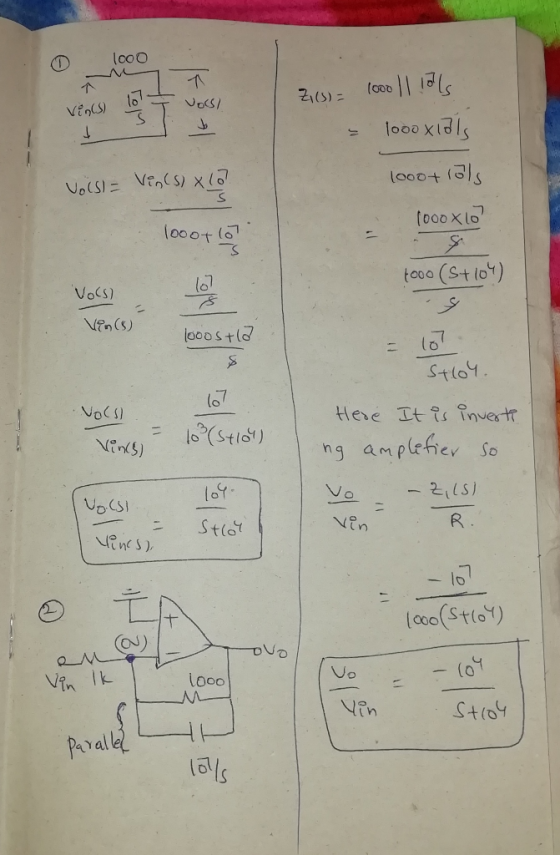
Calculate the transfer function of the two circuits.
Homework Answers
Add Answer to:
Calculate the transfer function of the two circuits.
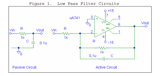
Figure 1. Low Pass Filter Circuits UA741 UA741...
1. Derive the transfer function for the low pass filter shown in Figure 1. The general...
 1. Derive the transfer function for the low pass filter shown in Figure 1. The general form is: H(s) w? W. s2 + +w? 2. Determine the component values by equating the derived transfer function to the general transfer function to meet the following specifications: a) fc = 2 kHz, and Q = 0.7071 for a Butterworth response. HH Vi R R C2 HHI Figure 1. Low-Pass Filter
This circuit is 3rd order low pass filter and i've got the simple euqation for the...
 This circuit is 3rd order low pass filter and i've got the
simple euqation for the transfer function. How can i get the exact
transfer functiion and find out the q factor and 3db point? thank
you
Vout Vin I R I jwC & R Vout a Vin - kill there Rt - I ljult (Ri tulich l
This circuit is 3rd order low pass filter and i've got the
simple euqation for the transfer function. How can i get the exact
transfer functiion and find out the q factor and 3db point? thank
you
Vout Vin I R I jwC & R Vout a Vin - kill there Rt - I ljult (Ri tulich l
We want to formulate the transfer function Vout/Vin and find out if it is low pass...
 We
want to formulate the transfer function Vout/Vin and find out if it
is low pass or high pass. Which answer choice is correct?
We want to formulate the transfer function VoUT(S)/VIN(s) and find out whether it is a low pa correct? ○ vout(s)/VIN(S)-(SUR) / (1 +SUR) and lowpass O VOUTtS)WIN(S)- 1/ (1+SL/R) and low pass 0 vout(s)/VIN(S)-1/ (1+5L/R) and high pass O VouT(S)NIN(S) (SUR)/ (1+s/R) and high pass
We
want to formulate the transfer function Vout/Vin and find out if it
is low pass or high pass. Which answer choice is correct?
We want to formulate the transfer function VoUT(S)/VIN(s) and find out whether it is a low pa correct? ○ vout(s)/VIN(S)-(SUR) / (1 +SUR) and lowpass O VOUTtS)WIN(S)- 1/ (1+SL/R) and low pass 0 vout(s)/VIN(S)-1/ (1+5L/R) and high pass O VouT(S)NIN(S) (SUR)/ (1+s/R) and high pass
- Vin R W Vout For the active low-pass filter above, calculate the break frequency in...
 - Vin R W Vout For the active low-pass filter above, calculate the break frequency in Hz and the low- frequency gain in dB if R1 = 47 k22, R2 = 820 k22 and C = 100 pF.
Active Low-pass and High-pass Filters for Crossover Circuitry (PSPICE) Design a first order active high-pass filter...
 Active Low-pass and High-pass Filters for Crossover Circuitry
(PSPICE)
Design a first order active high-pass filter with cut-off
frequency of 1 kHz & gain 20dB.
Design a first order active low-pass filter with cut-off
frequency of 1 kHz & gain 20dB.
Plot the magnitude and phase responses of the active high-pass
and low-pass filters you have designed using PSpice (Use UA741 Op
amp and ±12V dual supply).
Connect your active low-pass and high-pass filters as shown in
Fig. 1-b. Assume...
Active Low-pass and High-pass Filters for Crossover Circuitry
(PSPICE)
Design a first order active high-pass filter with cut-off
frequency of 1 kHz & gain 20dB.
Design a first order active low-pass filter with cut-off
frequency of 1 kHz & gain 20dB.
Plot the magnitude and phase responses of the active high-pass
and low-pass filters you have designed using PSpice (Use UA741 Op
amp and ±12V dual supply).
Connect your active low-pass and high-pass filters as shown in
Fig. 1-b. Assume...
Please answer all parts thank you 6. [15 POINTS] Consider a passive low-pass filter as shown...
 Please answer all parts thank
you
6. [15 POINTS] Consider a passive low-pass filter as shown below. 1k2 + - m - + Vin(t) 1 mF Vout(t) a) Derive a transfer function for the above circuit. b) Derive a time-domain expression for the unit impulse response of the circuit. Also, plot the impulse response as a function of time. c) Derive a time-domain expression for the unit step response of the circuit. Also, plot the step response as a function...
Please answer all parts thank
you
6. [15 POINTS] Consider a passive low-pass filter as shown below. 1k2 + - m - + Vin(t) 1 mF Vout(t) a) Derive a transfer function for the above circuit. b) Derive a time-domain expression for the unit impulse response of the circuit. Also, plot the impulse response as a function of time. c) Derive a time-domain expression for the unit step response of the circuit. Also, plot the step response as a function...
R 1800 с 220 pF 220 pF VIN VOUT R 1800 kn R1 12 ko R2...
 R 1800 с 220 pF 220 pF VIN VOUT R 1800 kn R1 12 ko R2 10 k Figure A-6. 14. Look at the circuit that's shown in Figure A-6. This circuit is a A. two-pole high-pass filter. B. two pole low-pass filter. C. two-pole passive filter. D. three-pole active filter.
What is the answer to question 23.1? 23.1 Active low-pass filter You can make a low-pass...
 What is the answer to question
23.1?
23.1 Active low-pass filter You can make a low-pass filter by putting a capacitor Cr and resistor Rf in parallel for Zj as shown in Figure 23.1. At low frequencies (well below the corner frequency), the feedback impedance is approximately Rf and the gain of a non-inverting amplifier is is 1 +R//R,. At high frequencies (well above the corner frequency),the impedance is approx- imately 1/(jwCs), and the gain of a non-inverting amplifier is...
What is the answer to question
23.1?
23.1 Active low-pass filter You can make a low-pass filter by putting a capacitor Cr and resistor Rf in parallel for Zj as shown in Figure 23.1. At low frequencies (well below the corner frequency), the feedback impedance is approximately Rf and the gain of a non-inverting amplifier is is 1 +R//R,. At high frequencies (well above the corner frequency),the impedance is approx- imately 1/(jwCs), and the gain of a non-inverting amplifier is...
C V. Figure 2 A band-pass filter circuit This is the transfer function of a band-pass...
 C V. Figure 2 A band-pass filter circuit This is the transfer function of a band-pass filter having R = R2 //R Center frequency, a[ 1/R' R C12 radians Bandwidth B2(R, C) radians Maximum Gain Ag- R/2R Band-Pass Filter Design Design a band-pass filter to obtain f-160 Hz, B-16 Hz and o- 10. Supply voltages of +20 and -20 Volts are available. Laboratory Measurements and Results . By applying sinusoidal voltage at the input and by varying its frequency, obtain...
Question 11 1 pts The transfer function of a particular active low pass filter is G(s)...
 Question 11 1 pts The transfer function of a particular active low pass filter is G(s) = 400/[s(1+0.8s)(1+0.15)). The phase shift in degrees through the filter at a frequency of 100 Hz is determined as nearest to which of the following answers:- -13 degrees 0 -63 degrees -123 degrees O 198 degrees O-269 degrees
 1. Derive the transfer function for the low pass filter shown in Figure 1. The general form is: H(s) w? W. s2 + +w? 2. Determine the component values by equating the derived transfer function to the general transfer function to meet the following specifications: a) fc = 2 kHz, and Q = 0.7071 for a Butterworth response. HH Vi R R C2 HHI Figure 1. Low-Pass Filter
 This circuit is 3rd order low pass filter and i've got the
simple euqation for the transfer function. How can i get the exact
transfer functiion and find out the q factor and 3db point? thank
you
Vout Vin I R I jwC & R Vout a Vin - kill there Rt - I ljult (Ri tulich l
This circuit is 3rd order low pass filter and i've got the
simple euqation for the transfer function. How can i get the exact
transfer functiion and find out the q factor and 3db point? thank
you
Vout Vin I R I jwC & R Vout a Vin - kill there Rt - I ljult (Ri tulich l
 We
want to formulate the transfer function Vout/Vin and find out if it
is low pass or high pass. Which answer choice is correct?
We want to formulate the transfer function VoUT(S)/VIN(s) and find out whether it is a low pa correct? ○ vout(s)/VIN(S)-(SUR) / (1 +SUR) and lowpass O VOUTtS)WIN(S)- 1/ (1+SL/R) and low pass 0 vout(s)/VIN(S)-1/ (1+5L/R) and high pass O VouT(S)NIN(S) (SUR)/ (1+s/R) and high pass
We
want to formulate the transfer function Vout/Vin and find out if it
is low pass or high pass. Which answer choice is correct?
We want to formulate the transfer function VoUT(S)/VIN(s) and find out whether it is a low pa correct? ○ vout(s)/VIN(S)-(SUR) / (1 +SUR) and lowpass O VOUTtS)WIN(S)- 1/ (1+SL/R) and low pass 0 vout(s)/VIN(S)-1/ (1+5L/R) and high pass O VouT(S)NIN(S) (SUR)/ (1+s/R) and high pass
 - Vin R W Vout For the active low-pass filter above, calculate the break frequency in Hz and the low- frequency gain in dB if R1 = 47 k22, R2 = 820 k22 and C = 100 pF.
 Active Low-pass and High-pass Filters for Crossover Circuitry
(PSPICE)
Design a first order active high-pass filter with cut-off
frequency of 1 kHz & gain 20dB.
Design a first order active low-pass filter with cut-off
frequency of 1 kHz & gain 20dB.
Plot the magnitude and phase responses of the active high-pass
and low-pass filters you have designed using PSpice (Use UA741 Op
amp and ±12V dual supply).
Connect your active low-pass and high-pass filters as shown in
Fig. 1-b. Assume...
Active Low-pass and High-pass Filters for Crossover Circuitry
(PSPICE)
Design a first order active high-pass filter with cut-off
frequency of 1 kHz & gain 20dB.
Design a first order active low-pass filter with cut-off
frequency of 1 kHz & gain 20dB.
Plot the magnitude and phase responses of the active high-pass
and low-pass filters you have designed using PSpice (Use UA741 Op
amp and ±12V dual supply).
Connect your active low-pass and high-pass filters as shown in
Fig. 1-b. Assume...
 Please answer all parts thank
you
6. [15 POINTS] Consider a passive low-pass filter as shown below. 1k2 + - m - + Vin(t) 1 mF Vout(t) a) Derive a transfer function for the above circuit. b) Derive a time-domain expression for the unit impulse response of the circuit. Also, plot the impulse response as a function of time. c) Derive a time-domain expression for the unit step response of the circuit. Also, plot the step response as a function...
Please answer all parts thank
you
6. [15 POINTS] Consider a passive low-pass filter as shown below. 1k2 + - m - + Vin(t) 1 mF Vout(t) a) Derive a transfer function for the above circuit. b) Derive a time-domain expression for the unit impulse response of the circuit. Also, plot the impulse response as a function of time. c) Derive a time-domain expression for the unit step response of the circuit. Also, plot the step response as a function...
 R 1800 с 220 pF 220 pF VIN VOUT R 1800 kn R1 12 ko R2 10 k Figure A-6. 14. Look at the circuit that's shown in Figure A-6. This circuit is a A. two-pole high-pass filter. B. two pole low-pass filter. C. two-pole passive filter. D. three-pole active filter.
 What is the answer to question
23.1?
23.1 Active low-pass filter You can make a low-pass filter by putting a capacitor Cr and resistor Rf in parallel for Zj as shown in Figure 23.1. At low frequencies (well below the corner frequency), the feedback impedance is approximately Rf and the gain of a non-inverting amplifier is is 1 +R//R,. At high frequencies (well above the corner frequency),the impedance is approx- imately 1/(jwCs), and the gain of a non-inverting amplifier is...
What is the answer to question
23.1?
23.1 Active low-pass filter You can make a low-pass filter by putting a capacitor Cr and resistor Rf in parallel for Zj as shown in Figure 23.1. At low frequencies (well below the corner frequency), the feedback impedance is approximately Rf and the gain of a non-inverting amplifier is is 1 +R//R,. At high frequencies (well above the corner frequency),the impedance is approx- imately 1/(jwCs), and the gain of a non-inverting amplifier is...
 C V. Figure 2 A band-pass filter circuit This is the transfer function of a band-pass filter having R = R2 //R Center frequency, a[ 1/R' R C12 radians Bandwidth B2(R, C) radians Maximum Gain Ag- R/2R Band-Pass Filter Design Design a band-pass filter to obtain f-160 Hz, B-16 Hz and o- 10. Supply voltages of +20 and -20 Volts are available. Laboratory Measurements and Results . By applying sinusoidal voltage at the input and by varying its frequency, obtain...
 Question 11 1 pts The transfer function of a particular active low pass filter is G(s) = 400/[s(1+0.8s)(1+0.15)). The phase shift in degrees through the filter at a frequency of 100 Hz is determined as nearest to which of the following answers:- -13 degrees 0 -63 degrees -123 degrees O 198 degrees O-269 degrees
Most questions answered within 3 hours.
-
Discuss in 500 words your opinion on what lessons should be
learned from the 737 Max...
asked 4 minutes ago -
100.0 g of nitrogen and 200.0 g of carbon dioxide are added at
25 ◦C into...
asked 4 minutes ago -
In JAVA: For this question, you need to create two interface
programs in a package and...
asked 18 minutes ago -
You notice that in early spring there is an equal distribution
of two different species of...
asked 15 minutes ago -
A
bullet is fired with a velocity of 200.0 m/s from the ground an
angle of...
asked 15 minutes ago -
Please answer the below 3 problems and show your work.
a. P(-1.45 < Z < .98)...
asked 14 minutes ago -
The inlet pressure of a steam generator is to be held constant
at 5.00 MPa. During...
asked 17 minutes ago -
QUESTION 31
In grid computing, the slowest computer creates a bottleneck and
slows down the entire...
asked 29 minutes ago -
A 236-m-wide river flows due east at a uniform speed of 2.1 m/s.
A boat with...
asked 37 minutes ago -
Here are the results of a monthly index model of stock returns
for FinCorp Stock: r(Fincorp)...
asked 29 minutes ago -
Answer the following questions based on this following business
startup idea:
Our business concept is individualized...
asked 39 minutes ago -
Red light of wavelength 650nm in air passes through two slits
submerged under water with n=1.33....
asked 33 minutes ago