
Homework Answers
Break frequency= 1940.91Hz
Low frequency gain in dB= 24.83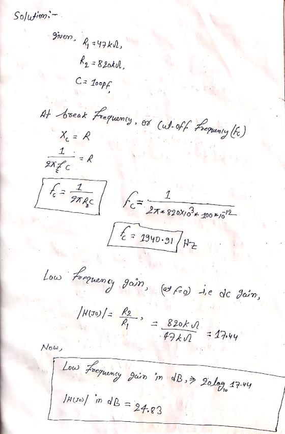
Add Answer to:
- Vin R W Vout For the active low-pass filter above, calculate the break frequency in...
R 1800 с 220 pF 220 pF VIN VOUT R 1800 kn R1 12 ko R2...
 R 1800 с 220 pF 220 pF VIN VOUT R 1800 kn R1 12 ko R2 10 k Figure A-6. 14. Look at the circuit that's shown in Figure A-6. This circuit is a A. two-pole high-pass filter. B. two pole low-pass filter. C. two-pole passive filter. D. three-pole active filter.
What kind of filter is this? Vout C W + Vin R not a filter band...
 What kind of filter is this? Vout C W + Vin R not a filter band stop high pass band pass low pass
design an active low pass filter with cutoff frequency of 400 hz and gain of 10...
design an active low pass filter with cutoff frequency of 400 hz and gain of 10 db at dc
TE Question 5 (20 marks) An active filter circuit is shown in Fig. 4. The cut-off frequency of this active filter is...
 TE Question 5 (20 marks) An active filter circuit is shown in Fig. 4. The cut-off frequency of this active filter is 1590Hz. The Input impedance and voltage gain of this filter are 10k0 and -5VN respectively Vout R1 vin R2 C1 Fig. 4 By assuming the operational amplifier, A is ideal, answer the following questions: (a) () State the type of this active fiter. (i) Explain the characteristic of this active filter. [2 marks] 3 marks] (b) 0) Calculate...
What is the answer to question 23.1? 23.1 Active low-pass filter You can make a low-pass...
 What is the answer to question
23.1?
23.1 Active low-pass filter You can make a low-pass filter by putting a capacitor Cr and resistor Rf in parallel for Zj as shown in Figure 23.1. At low frequencies (well below the corner frequency), the feedback impedance is approximately Rf and the gain of a non-inverting amplifier is is 1 +R//R,. At high frequencies (well above the corner frequency),the impedance is approx- imately 1/(jwCs), and the gain of a non-inverting amplifier is...
What is the answer to question
23.1?
23.1 Active low-pass filter You can make a low-pass filter by putting a capacitor Cr and resistor Rf in parallel for Zj as shown in Figure 23.1. At low frequencies (well below the corner frequency), the feedback impedance is approximately Rf and the gain of a non-inverting amplifier is is 1 +R//R,. At high frequencies (well above the corner frequency),the impedance is approx- imately 1/(jwCs), and the gain of a non-inverting amplifier is...
I'm having trouble building this low-pass filter circuit on tinkerCAD. (a) Low-pass filter R www Frequency...
 I'm having trouble building
this low-pass filter circuit on tinkerCAD.
(a) Low-pass filter R www Frequency w с Vout = VC 2.00 V 3.00 Hz 10.0 V 10 ri n 0.00 V 1.00 s LZ . NM +
I'm having trouble building
this low-pass filter circuit on tinkerCAD.
(a) Low-pass filter R www Frequency w с Vout = VC 2.00 V 3.00 Hz 10.0 V 10 ri n 0.00 V 1.00 s LZ . NM +
Design an active band-pass filter such that the center frequency is Fo-2.5 kHz, bandwidth is BW...
 Design an active band-pass filter such that the center frequency is Fo-2.5 kHz, bandwidth is BW 400 Hz and gain is K-3 for Figure 10.5. Find the values for the capacitors, and resistors. Compute the theoretical values of Vout and |Av Vout / V l and record the results in Table 10.5-A. VEE -15V C1 R3 C2 R1 R2 Vout +VCC +15V Figure 10.5
Design a low pass filter with a cutoff frequency of 1 kHz +/- 100 Hz and...
Design a low pass filter with a cutoff frequency of 1 kHz +/- 100 Hz and a gain of 16.0 dB +/- 1.0 dB in the passband. The R2 and C components of the filter control the cutoff frequency, and are inversely proportional to the cutoff frequency. So decreasing the resistance or capacitance will increase the cutoff frequency. The R1 and Rf components determine the gain of the amplifier. Increasing the value of Rf will increase the gain. Increasing the...
Amplificabon R3 Av Vin C1- R2 R1 Follow the instructions: 11. Connect the last circuit on the sim...
 Amplificabon R3 Av Vin C1- R2 R1 Follow the instructions: 11. Connect the last circuit on the simulation program. 12. Set Vin-3 V (rms) 13. R1-15 KO, R2-30 ΚΩ 14. R3s 20 КО, С. 10 nf 15, Op.Amp (741) Measure and calculate all the needed in the table: f(Hz) 150-1100 1200 I 600 I 800 1K | 2K Vo (V) Av Av (dB) 7. Plot a skitch of curve between F and Av(dB). (Frequency Response) -10 20 10 Hz 20...
A) Design a low-pass filter using the given circuitry with a cut-off value of 1 kHz and plot the ...
 a) Design a low-pass filter using the given circuitry with a cut-off value of 1 kHz and plot the frequency response curve on the given axes 1.0 0.7 0.5 in out 0.0 101 102 103 104 10s Hz b) Design a band-pass filter using the given circuitry with a bandwidth of 500 Hz and a lower cut-off value of 100 Hz, and draw the frequency response curve. Keep all resistors at the same value (i.e. Ri-R-R3-R4). 1.0 0.7 0.5 0.0...
 R 1800 с 220 pF 220 pF VIN VOUT R 1800 kn R1 12 ko R2 10 k Figure A-6. 14. Look at the circuit that's shown in Figure A-6. This circuit is a A. two-pole high-pass filter. B. two pole low-pass filter. C. two-pole passive filter. D. three-pole active filter.
 What kind of filter is this? Vout C W + Vin R not a filter band stop high pass band pass low pass
 TE Question 5 (20 marks) An active filter circuit is shown in Fig. 4. The cut-off frequency of this active filter is 1590Hz. The Input impedance and voltage gain of this filter are 10k0 and -5VN respectively Vout R1 vin R2 C1 Fig. 4 By assuming the operational amplifier, A is ideal, answer the following questions: (a) () State the type of this active fiter. (i) Explain the characteristic of this active filter. [2 marks] 3 marks] (b) 0) Calculate...
 What is the answer to question
23.1?
23.1 Active low-pass filter You can make a low-pass filter by putting a capacitor Cr and resistor Rf in parallel for Zj as shown in Figure 23.1. At low frequencies (well below the corner frequency), the feedback impedance is approximately Rf and the gain of a non-inverting amplifier is is 1 +R//R,. At high frequencies (well above the corner frequency),the impedance is approx- imately 1/(jwCs), and the gain of a non-inverting amplifier is...
What is the answer to question
23.1?
23.1 Active low-pass filter You can make a low-pass filter by putting a capacitor Cr and resistor Rf in parallel for Zj as shown in Figure 23.1. At low frequencies (well below the corner frequency), the feedback impedance is approximately Rf and the gain of a non-inverting amplifier is is 1 +R//R,. At high frequencies (well above the corner frequency),the impedance is approx- imately 1/(jwCs), and the gain of a non-inverting amplifier is...
 I'm having trouble building
this low-pass filter circuit on tinkerCAD.
(a) Low-pass filter R www Frequency w с Vout = VC 2.00 V 3.00 Hz 10.0 V 10 ri n 0.00 V 1.00 s LZ . NM +
I'm having trouble building
this low-pass filter circuit on tinkerCAD.
(a) Low-pass filter R www Frequency w с Vout = VC 2.00 V 3.00 Hz 10.0 V 10 ri n 0.00 V 1.00 s LZ . NM +
 Design an active band-pass filter such that the center frequency is Fo-2.5 kHz, bandwidth is BW 400 Hz and gain is K-3 for Figure 10.5. Find the values for the capacitors, and resistors. Compute the theoretical values of Vout and |Av Vout / V l and record the results in Table 10.5-A. VEE -15V C1 R3 C2 R1 R2 Vout +VCC +15V Figure 10.5
 Amplificabon R3 Av Vin C1- R2 R1 Follow the instructions: 11. Connect the last circuit on the simulation program. 12. Set Vin-3 V (rms) 13. R1-15 KO, R2-30 ΚΩ 14. R3s 20 КО, С. 10 nf 15, Op.Amp (741) Measure and calculate all the needed in the table: f(Hz) 150-1100 1200 I 600 I 800 1K | 2K Vo (V) Av Av (dB) 7. Plot a skitch of curve between F and Av(dB). (Frequency Response) -10 20 10 Hz 20...
 a) Design a low-pass filter using the given circuitry with a cut-off value of 1 kHz and plot the frequency response curve on the given axes 1.0 0.7 0.5 in out 0.0 101 102 103 104 10s Hz b) Design a band-pass filter using the given circuitry with a bandwidth of 500 Hz and a lower cut-off value of 100 Hz, and draw the frequency response curve. Keep all resistors at the same value (i.e. Ri-R-R3-R4). 1.0 0.7 0.5 0.0...
Most questions answered within 3 hours.
-
1) A loan of RM 10,000 at a flat rate of 10% per annum was
repaid...
asked 3 minutes ago -
Suppose you have been following a particular airline stock for
many years. You are interested in...
asked 10 minutes ago -
Describe the organic pasta: Is it a normal/inferior
good? Is it a necessity/luxury? Does it have...
asked 11 minutes ago -
Are Republicans just as likely as Democrats to display the
American flag in front of their...
asked 20 minutes ago -
Select the true statement below.
nitrogen dioxide is a stronger potential oxidizing agent than
dinitrogen monoxide...
asked 24 minutes ago -
What’s the probability of getting a sequence of 1,2,3,4,5,6 if
we roll a dice six times?
asked 26 minutes ago -
Ibarra Corporation uses the FIFO method in its process costing
system. The first processing department, the...
asked 26 minutes ago -
Multiple Choice Question:
Jennifer Jones, a 38-year-old employee at a metal fabricating
plant, was injured in...
asked 30 minutes ago -
Assume that adults have IQ scores that are normally distributed
with a mean of µ =105...
asked 43 minutes ago -
Self-Study Problem 12.3
Part a:
Linda filed her tax return 2 months late. The tax paid...
asked 45 minutes ago -
1. How many MOLECULES of
boron trichloride are present in
8.03 grams of this compound ?...
asked 57 minutes ago -
var gArr = [
{food: 'apple', type: 'fruit'},
{food: 'potato', type: 'vegetable'},
{food: 'banana', type: 'fruit'}...
asked 1 hour ago