
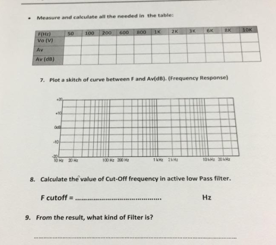
Measure and calculate all the needed in the table: f(Hz) 150-1100 1200 I 600 I 800 1K | 2K Vo (V) Av Av (dB) 7. Plot a skitch of curve between F and Av(dB). (Frequency Response) -10 20 10 Hz 20 Hz 100 H: 200 Hz 1kHz 2H 8. Calculate the value of Cut-Off frequency in active low Pass filter. Hz 9. From the result, what kind of Filter is?
Homework Answers


Add Answer to:
Amplificabon R3 Av Vin C1- R2 R1 Follow the instructions: 11. Connect the last circuit on the sim...
R2 R3 R1 C1 C2 S2 51 In the circuit, the signal frequency f = 1.2 MHz, R1=9 Ohm, R2 = 8 Ohm, R3 =...
 PLEASE HELP IMMEDIATELY
R2 R3 R1 C1 C2 S2 51 In the circuit, the signal frequency f = 1.2 MHz, R1=9 Ohm, R2 = 8 Ohm, R3 = 7 Ohm, C1-22 nF, C2=25 nF; The voltage source Vs1 amplitude and phase are 15 V and 0.12 rad; the voltage source Vs2 amplitude and phase are 4 V and 0.4 rad. (Note the polarity of the voltage sources!) Using nodal analysis, find the following 1) The amplitude of the potential at...
PLEASE HELP IMMEDIATELY
R2 R3 R1 C1 C2 S2 51 In the circuit, the signal frequency f = 1.2 MHz, R1=9 Ohm, R2 = 8 Ohm, R3 = 7 Ohm, C1-22 nF, C2=25 nF; The voltage source Vs1 amplitude and phase are 15 V and 0.12 rad; the voltage source Vs2 amplitude and phase are 4 V and 0.4 rad. (Note the polarity of the voltage sources!) Using nodal analysis, find the following 1) The amplitude of the potential at...
Simulation For each filter mentioned in the following cases, first simulate the circuit using Multisim. You can get a plot of the transfer function that is called the Bode plot. From the right toolba...
 Simulation For each filter mentioned in the following cases, first simulate the circuit using Multisim. You can get a plot of the transfer function that is called the Bode plot. From the right toolbar, select "Bode Plotter". Change initial (I) and final (F) frequencies to 1Hz and 200 KHz, respectively. Use a Voltage AC source as the input signal. You do not need to change any parameter from voltage AC source. Connect "Bode Plotter" to input and output of your...
Given the circuit below: R3 C1 Vout C2 R1 R3 Vin R2 ts 1 a) derive the transfer function between ...
 Given the circuit below: R3 C1 Vout C2 R1 R3 Vin R2 ts 1 a) derive the transfer function between the input and the output in terms of R1,C1,R2,C2 b) For this and all other parts below, assume Izl<Ipl, i..e that D(s) is a lead-type compensator. The transfer function is written in the following format ts 1 Express quantities K, z, p using R1,C1,R2,C2 Also, express Κα, α, τ using K,z, p c) Observe the values of s-jw on the...
Need to create a bandpass filter with cutoff frequencies from 300Hz to 3000Hz with a op-amp included in circuit. I have...
 Need to create a bandpass filter with cutoff frequencies from
300Hz to 3000Hz with a op-amp included in circuit. I have examples
below. you can use multisim, Pspice, or matlab for simulation of
circuit. I will up vote. Thanks.
Band-Pass Jitte L 300 H2 2R Ra C ХВР1 C1 IN OUT R2 53.10 1pF V1 R1 5310 6Vpk 1KHZ 0° BODE PLOT BODE PLOT m Design 000 50 00 -N00 00 - 150 00 Cune -20000 Bode Reault 100G 100...
Need to create a bandpass filter with cutoff frequencies from
300Hz to 3000Hz with a op-amp included in circuit. I have examples
below. you can use multisim, Pspice, or matlab for simulation of
circuit. I will up vote. Thanks.
Band-Pass Jitte L 300 H2 2R Ra C ХВР1 C1 IN OUT R2 53.10 1pF V1 R1 5310 6Vpk 1KHZ 0° BODE PLOT BODE PLOT m Design 000 50 00 -N00 00 - 150 00 Cune -20000 Bode Reault 100G 100...
R1 C1 HH The V1 R2 11 R3 circuit shown is a simplified representation of a...
 R1 C1 HH The V1 R2 11 R3 circuit shown is a simplified representation of a small signal transistor amplifier circuit. The AC input voltage is V1, with angular frequency w. The current through R2, is It. The dependent current source, 11, has value 100 IV. Let R1 = 500, and R2 = 1000. The load resistor, R3 has a value that is selectable by a design engineer. Let C1 = 10 pF, and L1 = 1 uH. (For reference,...
For the electrical circuit below, let R1=30 Ohms, R2=15 Ohms, R3=10 Ohms, R4=20 Ohms, C=0.1 F...
 For the electrical circuit below, let R1=30 Ohms, R2=15 Ohms,
R3=10 Ohms, R4=20 Ohms, C=0.1 F and Vin=10V and complete the
following.
For the electrical circuit below, let R1 = 30 12, R2 = 152, R3 = 102, R1 = 20 2, C =0.1 F and Vin = 10V and complete the following. a) Use circuit analysis to derive the differential equation for the capacitor voltage, V.(t). b) Find the solution for V«(t) and sketch it for t=0, t and...
For the electrical circuit below, let R1=30 Ohms, R2=15 Ohms,
R3=10 Ohms, R4=20 Ohms, C=0.1 F and Vin=10V and complete the
following.
For the electrical circuit below, let R1 = 30 12, R2 = 152, R3 = 102, R1 = 20 2, C =0.1 F and Vin = 10V and complete the following. a) Use circuit analysis to derive the differential equation for the capacitor voltage, V.(t). b) Find the solution for V«(t) and sketch it for t=0, t and...
For the circuit shown below In terms of Vo. RI. R2, R3. R4 Cİ.t and s what is the time domain equation for the voltage at node out? Preview In terms of Vo, R1, R2, R3 R4, C1,t, and s what is the freq...
 For the circuit shown below In terms of Vo. RI. R2, R3. R4 Cİ.t and s what is the time domain equation for the voltage at node out? Preview In terms of Vo, R1, R2, R3 R4, C1,t, and s what is the frequency domain equation the voltage at node out? Preview In terms of Vo. R1. R2. R3. R4. Cl.t. and s what is the equation for t? Preview Ifthe voltage vi at tune-0 is 3 V RI"? kQ....
I need help to measure the high frequency cutoff. The circuit below is for HIGH PASS...
 I need help to measure the high frequency cutoff. The circuit
below is for HIGH PASS FILTER
I made it but I dont know how to accurately measure the high
cutoff as what we did in the lab. in the lab we get 14.35
kHz but when I try in the multisim and varing the freqency
as shown in the table below I dont get any change.
Please do it in multisim and explain your answer, thanks.
f
1-kHz
2-kHz...
I need help to measure the high frequency cutoff. The circuit
below is for HIGH PASS FILTER
I made it but I dont know how to accurately measure the high
cutoff as what we did in the lab. in the lab we get 14.35
kHz but when I try in the multisim and varing the freqency
as shown in the table below I dont get any change.
Please do it in multisim and explain your answer, thanks.
f
1-kHz
2-kHz...
 PLEASE HELP IMMEDIATELY
R2 R3 R1 C1 C2 S2 51 In the circuit, the signal frequency f = 1.2 MHz, R1=9 Ohm, R2 = 8 Ohm, R3 = 7 Ohm, C1-22 nF, C2=25 nF; The voltage source Vs1 amplitude and phase are 15 V and 0.12 rad; the voltage source Vs2 amplitude and phase are 4 V and 0.4 rad. (Note the polarity of the voltage sources!) Using nodal analysis, find the following 1) The amplitude of the potential at...
PLEASE HELP IMMEDIATELY
R2 R3 R1 C1 C2 S2 51 In the circuit, the signal frequency f = 1.2 MHz, R1=9 Ohm, R2 = 8 Ohm, R3 = 7 Ohm, C1-22 nF, C2=25 nF; The voltage source Vs1 amplitude and phase are 15 V and 0.12 rad; the voltage source Vs2 amplitude and phase are 4 V and 0.4 rad. (Note the polarity of the voltage sources!) Using nodal analysis, find the following 1) The amplitude of the potential at...
 Simulation For each filter mentioned in the following cases, first simulate the circuit using Multisim. You can get a plot of the transfer function that is called the Bode plot. From the right toolbar, select "Bode Plotter". Change initial (I) and final (F) frequencies to 1Hz and 200 KHz, respectively. Use a Voltage AC source as the input signal. You do not need to change any parameter from voltage AC source. Connect "Bode Plotter" to input and output of your...
 Given the circuit below: R3 C1 Vout C2 R1 R3 Vin R2 ts 1 a) derive the transfer function between the input and the output in terms of R1,C1,R2,C2 b) For this and all other parts below, assume Izl<Ipl, i..e that D(s) is a lead-type compensator. The transfer function is written in the following format ts 1 Express quantities K, z, p using R1,C1,R2,C2 Also, express Κα, α, τ using K,z, p c) Observe the values of s-jw on the...
 Need to create a bandpass filter with cutoff frequencies from
300Hz to 3000Hz with a op-amp included in circuit. I have examples
below. you can use multisim, Pspice, or matlab for simulation of
circuit. I will up vote. Thanks.
Band-Pass Jitte L 300 H2 2R Ra C ХВР1 C1 IN OUT R2 53.10 1pF V1 R1 5310 6Vpk 1KHZ 0° BODE PLOT BODE PLOT m Design 000 50 00 -N00 00 - 150 00 Cune -20000 Bode Reault 100G 100...
Need to create a bandpass filter with cutoff frequencies from
300Hz to 3000Hz with a op-amp included in circuit. I have examples
below. you can use multisim, Pspice, or matlab for simulation of
circuit. I will up vote. Thanks.
Band-Pass Jitte L 300 H2 2R Ra C ХВР1 C1 IN OUT R2 53.10 1pF V1 R1 5310 6Vpk 1KHZ 0° BODE PLOT BODE PLOT m Design 000 50 00 -N00 00 - 150 00 Cune -20000 Bode Reault 100G 100...
 R1 C1 HH The V1 R2 11 R3 circuit shown is a simplified representation of a small signal transistor amplifier circuit. The AC input voltage is V1, with angular frequency w. The current through R2, is It. The dependent current source, 11, has value 100 IV. Let R1 = 500, and R2 = 1000. The load resistor, R3 has a value that is selectable by a design engineer. Let C1 = 10 pF, and L1 = 1 uH. (For reference,...
 For the electrical circuit below, let R1=30 Ohms, R2=15 Ohms,
R3=10 Ohms, R4=20 Ohms, C=0.1 F and Vin=10V and complete the
following.
For the electrical circuit below, let R1 = 30 12, R2 = 152, R3 = 102, R1 = 20 2, C =0.1 F and Vin = 10V and complete the following. a) Use circuit analysis to derive the differential equation for the capacitor voltage, V.(t). b) Find the solution for V«(t) and sketch it for t=0, t and...
For the electrical circuit below, let R1=30 Ohms, R2=15 Ohms,
R3=10 Ohms, R4=20 Ohms, C=0.1 F and Vin=10V and complete the
following.
For the electrical circuit below, let R1 = 30 12, R2 = 152, R3 = 102, R1 = 20 2, C =0.1 F and Vin = 10V and complete the following. a) Use circuit analysis to derive the differential equation for the capacitor voltage, V.(t). b) Find the solution for V«(t) and sketch it for t=0, t and...
 For the circuit shown below In terms of Vo. RI. R2, R3. R4 Cİ.t and s what is the time domain equation for the voltage at node out? Preview In terms of Vo, R1, R2, R3 R4, C1,t, and s what is the frequency domain equation the voltage at node out? Preview In terms of Vo. R1. R2. R3. R4. Cl.t. and s what is the equation for t? Preview Ifthe voltage vi at tune-0 is 3 V RI"? kQ....
 I need help to measure the high frequency cutoff. The circuit
below is for HIGH PASS FILTER
I made it but I dont know how to accurately measure the high
cutoff as what we did in the lab. in the lab we get 14.35
kHz but when I try in the multisim and varing the freqency
as shown in the table below I dont get any change.
Please do it in multisim and explain your answer, thanks.
f
1-kHz
2-kHz...
I need help to measure the high frequency cutoff. The circuit
below is for HIGH PASS FILTER
I made it but I dont know how to accurately measure the high
cutoff as what we did in the lab. in the lab we get 14.35
kHz but when I try in the multisim and varing the freqency
as shown in the table below I dont get any change.
Please do it in multisim and explain your answer, thanks.
f
1-kHz
2-kHz...
Most questions answered within 3 hours.
-
You look at yourself in a shiny 9.6-cm-diameter Christmas tree
ball.
If your face is 21.0...
asked 27 seconds ago -
If we were to measure the relaxation time of a muscle after
undergoing tetanus compared to...
asked 9 seconds ago -
4CO(g) + 8H2(g) -----> 3CH4(g) +
CO2(g) + 2H2O(l)
Use the following data as needed to...
asked 3 minutes ago -
without using map
1. Write a C++ program to find out the top 10 words in...
asked 16 minutes ago -
1)Calculate the percent ionization of a
0.330 M solution of hypochlorous
acid.
% Ionization = %...
asked 19 minutes ago -
1a) How many grams of K2SO4 are in 250mL
of 0.11 M K2SO4 solution?
_____ g...
asked 10 minutes ago -
The vapor pressure of a solution containing 38.7 g glycerin
(C3H8O3) in 146.2 g ethanol (C2H5OH)...
asked 15 minutes ago -
A physics major is cooking breakfast when he notices that the
frictional force between the steel...
asked 20 minutes ago -
A cyclohexane (c-hex) solution is prepared by fully dissolving
9.11g of a newly synthesized organic compound...
asked 26 minutes ago -
SCHEME :-)
[5 marks] Write a procedure called convert that takes as
arguments: a temperature value...
asked 32 minutes ago -
Are
Acetyl CoA and Pyruvate biological molecules that are used to get
ATP energy in aerobic...
asked 34 minutes ago -
Two waves are traveling on a string, one with a wave function,
y1 = 0.05sin(4x -...
asked 41 minutes ago