
Homework Answers

- Vin R W Vout For the active low-pass filter above, calculate the break frequency in...
 - Vin R W Vout For the active low-pass filter above, calculate the break frequency in Hz and the low- frequency gain in dB if R1 = 47 k22, R2 = 820 k22 and C = 100 pF.
What type of filter is the circuit? a) Low Pass b) High pass c) Band stop...
 What type of filter is the circuit? a) Low Pass b) High pass c) Band stop d) Band pass What type of filter is the circuit? a) Low pass b) high pass c) band stop d) band pass I + What type of filter is the circuit? a) Band Pass b) Low pass c) Band stop d) High pass
R Vin(s) - Vout(s) For the above given RL circuit, a) (10p) Please define whether it...
 R Vin(s) - Vout(s) For the above given RL circuit, a) (10p) Please define whether it is high-pass, low-pass or band-pass filter, b) (20p) Calculate R value for L-5 mH and fc-1496 hertz, e) (20p) Calculate L value for R-62 and fc-1973.5 hertz
R 1800 с 220 pF 220 pF VIN VOUT R 1800 kn R1 12 ko R2...
 R 1800 с 220 pF 220 pF VIN VOUT R 1800 kn R1 12 ko R2 10 k Figure A-6. 14. Look at the circuit that's shown in Figure A-6. This circuit is a A. two-pole high-pass filter. B. two pole low-pass filter. C. two-pole passive filter. D. three-pole active filter.
Mark with an X, the best answer for each statement below. Show your reasoning 9. EXTRA CREDIT: The ac circuit in Fig. 9(a), with the output VouT, acts as a: [2 points extra credit] a. 12 F Vin (t) 6...
 Mark with an X, the best answer for each statement below. Show your reasoning 9. EXTRA CREDIT: The ac circuit in Fig. 9(a), with the output VouT, acts as a: [2 points extra credit] a. 12 F Vin (t) 6 S2 low-pass filter (see Table Vourl t) band-pass filter (see Table) band-stop filter (see Table) high-pass filter (see Table) 12 H iv. V. Fig. 9 (a) _ None of the above Table: Filter Definitions Pass Stop Low-Pass b. For the...
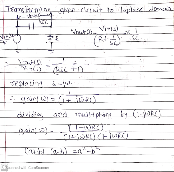
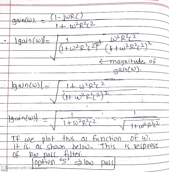
We want to formulate the transfer function Vout/Vin and find out if it is low pass...
 We
want to formulate the transfer function Vout/Vin and find out if it
is low pass or high pass. Which answer choice is correct?
We want to formulate the transfer function VoUT(S)/VIN(s) and find out whether it is a low pa correct? ○ vout(s)/VIN(S)-(SUR) / (1 +SUR) and lowpass O VOUTtS)WIN(S)- 1/ (1+SL/R) and low pass 0 vout(s)/VIN(S)-1/ (1+5L/R) and high pass O VouT(S)NIN(S) (SUR)/ (1+s/R) and high pass
We
want to formulate the transfer function Vout/Vin and find out if it
is low pass or high pass. Which answer choice is correct?
We want to formulate the transfer function VoUT(S)/VIN(s) and find out whether it is a low pa correct? ○ vout(s)/VIN(S)-(SUR) / (1 +SUR) and lowpass O VOUTtS)WIN(S)- 1/ (1+SL/R) and low pass 0 vout(s)/VIN(S)-1/ (1+5L/R) and high pass O VouT(S)NIN(S) (SUR)/ (1+s/R) and high pass
5) Consider the following second-order bandpass filter. As input voltage, apply V(t) 100Ω, C-4.7 μF. and L-10mH. sin(wt).R in Vout Fig 9: Second-order band-pass filter a) Determine the frequenc...
 5) Consider the following second-order bandpass filter. As input voltage, apply V(t) 100Ω, C-4.7 μF. and L-10mH. sin(wt).R in Vout Fig 9: Second-order band-pass filter a) Determine the frequency response function H(ju) Ve-ju) / Vm(ju) and sketch the magnitude and phase characteristics versus w by calaulation. Calculate the theoretical cutoff frequency of the filter Using PSpice AC analysis, plot magnitude lHju)l and phase ф characteristics of the filter, between 1 Hz-100 KHz b) c)
5) Consider the following second-order bandpass...
5) Consider the following second-order bandpass filter. As input voltage, apply V(t) 100Ω, C-4.7 μF. and L-10mH. sin(wt).R in Vout Fig 9: Second-order band-pass filter a) Determine the frequency response function H(ju) Ve-ju) / Vm(ju) and sketch the magnitude and phase characteristics versus w by calaulation. Calculate the theoretical cutoff frequency of the filter Using PSpice AC analysis, plot magnitude lHju)l and phase ф characteristics of the filter, between 1 Hz-100 KHz b) c)
5) Consider the following second-order bandpass...
What kind of filter has poles in the imaginary left half plane? (Low pass, high pass,...
What kind of filter has poles in the imaginary left half plane? (Low pass, high pass, band pass, or band reject). A brief explanation of the transfer function(s) would be great, I am having a hard time understanding the concept behind this. Thank you.
just do 4 , 3 is solved 3. Use a Bilinear Transform to design a Butterworth low-pass filter which satisfies the filter specifications: Pass band: -1Ss0 for 0sf s0.2 Stop band: (e/40 for 0.35sf s0....
 just do 4 , 3 is solved
3. Use a Bilinear Transform to design a Butterworth low-pass filter which satisfies the filter specifications: Pass band: -1Ss0 for 0sf s0.2 Stop band: (e/40 for 0.35sf s0.s Transition Band: 0.2<f<0.35 Sampling Frequency: 10 kHz a. (3) Determine the stop-band and pass-band frequencies, Fstop and Fpas, in kHz. b. (3) Calculate the fater order, n, which is necessary to obtain the desired filter specifications. (3) Calculate the corner frequency, Fe, if you want...
just do 4 , 3 is solved
3. Use a Bilinear Transform to design a Butterworth low-pass filter which satisfies the filter specifications: Pass band: -1Ss0 for 0sf s0.2 Stop band: (e/40 for 0.35sf s0.s Transition Band: 0.2<f<0.35 Sampling Frequency: 10 kHz a. (3) Determine the stop-band and pass-band frequencies, Fstop and Fpas, in kHz. b. (3) Calculate the fater order, n, which is necessary to obtain the desired filter specifications. (3) Calculate the corner frequency, Fe, if you want...
2. Consider the given C-R filter. a. (4) Determine the transfer function H(jo) in terms of...
 2. Consider the given C-R filter. a. (4) Determine the transfer function H(jo) in terms of R, C and o. b. (3) Express the transfer function in polar form i.e. find the magnitude and phase expressions. c. (3) Calculate the half-power or cut-off frequency of this filter in rad/s for R = 250 2 and C= 15 nF. d. (4) Plot the magnitude response H(jo) using linear scale. Label both axes. Label maxima, minima, and cut-off frequency points numerically on...
 - Vin R W Vout For the active low-pass filter above, calculate the break frequency in Hz and the low- frequency gain in dB if R1 = 47 k22, R2 = 820 k22 and C = 100 pF.
 What type of filter is the circuit? a) Low Pass b) High pass c) Band stop d) Band pass What type of filter is the circuit? a) Low pass b) high pass c) band stop d) band pass I + What type of filter is the circuit? a) Band Pass b) Low pass c) Band stop d) High pass
 R Vin(s) - Vout(s) For the above given RL circuit, a) (10p) Please define whether it is high-pass, low-pass or band-pass filter, b) (20p) Calculate R value for L-5 mH and fc-1496 hertz, e) (20p) Calculate L value for R-62 and fc-1973.5 hertz
 R 1800 с 220 pF 220 pF VIN VOUT R 1800 kn R1 12 ko R2 10 k Figure A-6. 14. Look at the circuit that's shown in Figure A-6. This circuit is a A. two-pole high-pass filter. B. two pole low-pass filter. C. two-pole passive filter. D. three-pole active filter.
 Mark with an X, the best answer for each statement below. Show your reasoning 9. EXTRA CREDIT: The ac circuit in Fig. 9(a), with the output VouT, acts as a: [2 points extra credit] a. 12 F Vin (t) 6 S2 low-pass filter (see Table Vourl t) band-pass filter (see Table) band-stop filter (see Table) high-pass filter (see Table) 12 H iv. V. Fig. 9 (a) _ None of the above Table: Filter Definitions Pass Stop Low-Pass b. For the...
 We
want to formulate the transfer function Vout/Vin and find out if it
is low pass or high pass. Which answer choice is correct?
We want to formulate the transfer function VoUT(S)/VIN(s) and find out whether it is a low pa correct? ○ vout(s)/VIN(S)-(SUR) / (1 +SUR) and lowpass O VOUTtS)WIN(S)- 1/ (1+SL/R) and low pass 0 vout(s)/VIN(S)-1/ (1+5L/R) and high pass O VouT(S)NIN(S) (SUR)/ (1+s/R) and high pass
We
want to formulate the transfer function Vout/Vin and find out if it
is low pass or high pass. Which answer choice is correct?
We want to formulate the transfer function VoUT(S)/VIN(s) and find out whether it is a low pa correct? ○ vout(s)/VIN(S)-(SUR) / (1 +SUR) and lowpass O VOUTtS)WIN(S)- 1/ (1+SL/R) and low pass 0 vout(s)/VIN(S)-1/ (1+5L/R) and high pass O VouT(S)NIN(S) (SUR)/ (1+s/R) and high pass
 5) Consider the following second-order bandpass filter. As input voltage, apply V(t) 100Ω, C-4.7 μF. and L-10mH. sin(wt).R in Vout Fig 9: Second-order band-pass filter a) Determine the frequency response function H(ju) Ve-ju) / Vm(ju) and sketch the magnitude and phase characteristics versus w by calaulation. Calculate the theoretical cutoff frequency of the filter Using PSpice AC analysis, plot magnitude lHju)l and phase ф characteristics of the filter, between 1 Hz-100 KHz b) c)
5) Consider the following second-order bandpass...
5) Consider the following second-order bandpass filter. As input voltage, apply V(t) 100Ω, C-4.7 μF. and L-10mH. sin(wt).R in Vout Fig 9: Second-order band-pass filter a) Determine the frequency response function H(ju) Ve-ju) / Vm(ju) and sketch the magnitude and phase characteristics versus w by calaulation. Calculate the theoretical cutoff frequency of the filter Using PSpice AC analysis, plot magnitude lHju)l and phase ф characteristics of the filter, between 1 Hz-100 KHz b) c)
5) Consider the following second-order bandpass...
 just do 4 , 3 is solved
3. Use a Bilinear Transform to design a Butterworth low-pass filter which satisfies the filter specifications: Pass band: -1Ss0 for 0sf s0.2 Stop band: (e/40 for 0.35sf s0.s Transition Band: 0.2<f<0.35 Sampling Frequency: 10 kHz a. (3) Determine the stop-band and pass-band frequencies, Fstop and Fpas, in kHz. b. (3) Calculate the fater order, n, which is necessary to obtain the desired filter specifications. (3) Calculate the corner frequency, Fe, if you want...
just do 4 , 3 is solved
3. Use a Bilinear Transform to design a Butterworth low-pass filter which satisfies the filter specifications: Pass band: -1Ss0 for 0sf s0.2 Stop band: (e/40 for 0.35sf s0.s Transition Band: 0.2<f<0.35 Sampling Frequency: 10 kHz a. (3) Determine the stop-band and pass-band frequencies, Fstop and Fpas, in kHz. b. (3) Calculate the fater order, n, which is necessary to obtain the desired filter specifications. (3) Calculate the corner frequency, Fe, if you want...
 2. Consider the given C-R filter. a. (4) Determine the transfer function H(jo) in terms of R, C and o. b. (3) Express the transfer function in polar form i.e. find the magnitude and phase expressions. c. (3) Calculate the half-power or cut-off frequency of this filter in rad/s for R = 250 2 and C= 15 nF. d. (4) Plot the magnitude response H(jo) using linear scale. Label both axes. Label maxima, minima, and cut-off frequency points numerically on...
Most questions answered within 3 hours.
-
A .15kg rubber ball is bounced off a wall. Before hitting the
wall, the ball moves...
asked 7 minutes ago -
A manufacturing company preparing to build a new plant is
considering three potential locations for it....
asked 9 minutes ago -
B. If compound Y has approximately the same values of solubility
in toluene as compound X,...
asked 55 minutes ago -
Oscar Inc. has inventory in Japan valued at 39,051,000 Yen one
year ago. One year ago...
asked 1 hour ago -
If Canada suffered from "fundamental disequilibrium," and its
government choose not to devalue its currency, a...
asked 1 hour ago -
4. How many input & output Key Value Pairs are passed into,
and emitted out of...
asked 1 hour ago -
Why would your heart not function well if constructed of
skeletal muscle? What is the particular...
asked 1 hour ago -
Please respond to this essay question in full essay form for
Chemistry 1102 Organic and Biochemistry:...
asked 1 hour ago -
Determine the head loss and velocity of flow in a water supply main
of 15.0 cm...
asked 1 hour ago -
A marketing executive who knowingly authorizes a shoddy
defective product to be brought to market is...
asked 1 hour ago -
Write a psudocode:
1. Define a function called authorize that takes in 2 strings,
uName, and...
asked 1 hour ago -
What Hall voltage (in mV) is produced by a 0.180 T field applied
across a 2.60...
asked 1 hour ago