Design a simplified logic circuit that counts the number of zeros in the input, the circuit...
Homework Answers


NOTE:-PLEASE IGNORE THE NOT GATE(INVERTERS)
PLEASE ASK YOUR DOUBT IN COMMENT.
PLEASE LIKE THE ANSWER.THANK YOU!!
ALL THE BEST!!
Add Answer to:
Design a simplified logic circuit that counts the number of zeros
in the input, the circuit...
DESIGN SECTION Before the experiment, you are going to design a circuit which has 4 inputs...
DESIGN SECTION Before the experiment, you are going to design a circuit which has 4 inputs w, x, y, z and an output F. If 4-bits input value is “odd number which is higher than 4”, or “3-bits highest even number” or “4-bits highest even number”, the output function F will be equal to 1. Otherwise F=0. Each students have to design the circuit and have to do following steps own by own. You are going to; a) Fill the...
Design the logic circuit to display a 3 bit octal numbers from 0 to 7 on...
 Design the logic circuit to display a 3 bit octal numbers from 0 to 7 on a seven segment display shown below (for number 1 use segments b and c; for 6 include segment (a) Write the Truth Table with A, B. C representing the input bits (A is the MSB) and a, b, c, d, e, f and g representing the outputs to the seven segments. (b) Implement the circuit using a Programmable Logic Array (use simplified notation to...
Design an elevator control which takes floor number (0, 1, 2, and 3) as input and...
 Design an elevator control which takes floor number (0, 1, 2, and 3) as input and outputs the direction of movement of the elevator (up (1), down(0), stay (2)) and the number of floors to move. Floors: 0, 1, 2, 3 (Ground, First, Second, Third) Input: Press the floor to move to button (0, 1, 2, 3) . o Present State- Current Floor o Next State Next Floor i.e., floor to move to Outputl up/down/stay (1/0/2) Output2 Floors to move...
all witworDFFs, FFI and FFo, two 4xI multiplexers, four 2-bit registers (Ro, RI, R2, and R3; all I with p arallel outputs) and no additional logic gates, design a circuit to support the following...
 all witworDFFs, FFI and FFo, two 4xI multiplexers, four 2-bit registers (Ro, RI, R2, and R3; all I with p arallel outputs) and no additional logic gates, design a circuit to support the following operations based on 2-bit inputs M1 and MO M1 MO values Operation (at the rising edge of the clock) RO FF1 FFO (bits of RO stored in FF1&FFO IFF1 FFO (bits of R1 stored in FF1&FFO R2 FF1 FFO (bits of R2 stored in FFI &FFO...
Design a combinational logic circuit which has one output Z and a 4-bit input ABCD representing...
Design a combinational logic circuit which has one output Z and a 4-bit input ABCD representing a binary number. Z should be 1 iff the input is at least 5, but is no greater than 11. Use one OR gate (three inputs) and three AND gates (with no more than three inputs each). Using K-map, find min SOP and min POS form for the outputs W, X
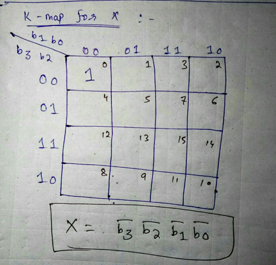
(a) Write a truth table. The input is 4-bit binary ABCD, A is MSB, D is...
 (a) Write a truth table. The input is 4-bit binary ABCD, A is
MSB, D is LSB. The output is also represented by x.
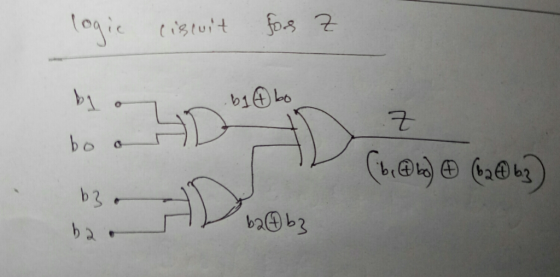
(b) Obtain an output expression in the form of a SOP.
(c) Use Boolean Algebra to design a circuit consisting of only
four inverters, four 3-input and gate, and one 4-input OR gate
using the simplified and simplified expression obtained in (b).
4-6. The Excess-3 coding system is a four-bit digital coding system for encoding all...
(a) Write a truth table. The input is 4-bit binary ABCD, A is
MSB, D is LSB. The output is also represented by x.
(b) Obtain an output expression in the form of a SOP.
(c) Use Boolean Algebra to design a circuit consisting of only
four inverters, four 3-input and gate, and one 4-input OR gate
using the simplified and simplified expression obtained in (b).
4-6. The Excess-3 coding system is a four-bit digital coding system for encoding all...
Acer Question Three Design a circuit with t wo inputs x & y representing the bits in a binary num...
 acer Question Three Design a circuit with t wo inputs x & y representing the bits in a binary number and outputs a& b also representing bits in a binary number. When t output is reversed. When the input is 1 and 3, the output s O and 2, the Any carry forward is discarded a) Show your truth table b) Find and simplify the Boolean expression for the o utputs a & b. c) Draw one logic circuit to...
Please send an easy to read circuit design as well and explain how it works. 4:02...
 Please send an easy to read circuit design as well and explain
how it works.
4:02 00 LTE il 50% + ENEE 2586 - Lab 9_f... @ + : ENEF 356 Lab -Sequence Detector ENEE 2586 Lab #9 - Sequence Detector Purpose: The goal of this lab is to design a sequence detector using sequential logic circuits Procedure: 1. Design a sequential logic circuit to check an input stream labeled X and to produce an output Z=1 for any input...
Please send an easy to read circuit design as well and explain
how it works.
4:02 00 LTE il 50% + ENEE 2586 - Lab 9_f... @ + : ENEF 356 Lab -Sequence Detector ENEE 2586 Lab #9 - Sequence Detector Purpose: The goal of this lab is to design a sequence detector using sequential logic circuits Procedure: 1. Design a sequential logic circuit to check an input stream labeled X and to produce an output Z=1 for any input...
Design a circuit that has a 3 bit binary input (representing 0 through 7) and outputs...
Design a circuit that has a 3 bit binary input (representing 0 through 7) and outputs a 1 if the input is a prime number. A prime number (or prime) is a natural number greater than 1 that has no positive divisors other than 1 and itself. a) Fill out a truth table that represents the logic equation for this circuit: Y = F(A,B,C). b) Using a Karnaugh map simplify the logic equation.
Design a combinational circuit that accepts a 3-bit binary number input x
Design a combinational circuit that accepts a 3-bit binary number input x and generates a 6-bit binary number output equal to the xth Fibonacci number F(x) = F(x-1) +F(x-2) where F(0) = 2 and F(1) = 3.The book we are using in class is this: http://www.cramster.com/logic-and-computer-design-fundamentals-4th-solutions-3631 and we are on chapter 3.
 Design the logic circuit to display a 3 bit octal numbers from 0 to 7 on a seven segment display shown below (for number 1 use segments b and c; for 6 include segment (a) Write the Truth Table with A, B. C representing the input bits (A is the MSB) and a, b, c, d, e, f and g representing the outputs to the seven segments. (b) Implement the circuit using a Programmable Logic Array (use simplified notation to...
 Design an elevator control which takes floor number (0, 1, 2, and 3) as input and outputs the direction of movement of the elevator (up (1), down(0), stay (2)) and the number of floors to move. Floors: 0, 1, 2, 3 (Ground, First, Second, Third) Input: Press the floor to move to button (0, 1, 2, 3) . o Present State- Current Floor o Next State Next Floor i.e., floor to move to Outputl up/down/stay (1/0/2) Output2 Floors to move...
 all witworDFFs, FFI and FFo, two 4xI multiplexers, four 2-bit registers (Ro, RI, R2, and R3; all I with p arallel outputs) and no additional logic gates, design a circuit to support the following operations based on 2-bit inputs M1 and MO M1 MO values Operation (at the rising edge of the clock) RO FF1 FFO (bits of RO stored in FF1&FFO IFF1 FFO (bits of R1 stored in FF1&FFO R2 FF1 FFO (bits of R2 stored in FFI &FFO...
 (a) Write a truth table. The input is 4-bit binary ABCD, A is
MSB, D is LSB. The output is also represented by x.
(b) Obtain an output expression in the form of a SOP.
(c) Use Boolean Algebra to design a circuit consisting of only
four inverters, four 3-input and gate, and one 4-input OR gate
using the simplified and simplified expression obtained in (b).
4-6. The Excess-3 coding system is a four-bit digital coding system for encoding all...
(a) Write a truth table. The input is 4-bit binary ABCD, A is
MSB, D is LSB. The output is also represented by x.
(b) Obtain an output expression in the form of a SOP.
(c) Use Boolean Algebra to design a circuit consisting of only
four inverters, four 3-input and gate, and one 4-input OR gate
using the simplified and simplified expression obtained in (b).
4-6. The Excess-3 coding system is a four-bit digital coding system for encoding all...
 acer Question Three Design a circuit with t wo inputs x & y representing the bits in a binary number and outputs a& b also representing bits in a binary number. When t output is reversed. When the input is 1 and 3, the output s O and 2, the Any carry forward is discarded a) Show your truth table b) Find and simplify the Boolean expression for the o utputs a & b. c) Draw one logic circuit to...
 Please send an easy to read circuit design as well and explain
how it works.
4:02 00 LTE il 50% + ENEE 2586 - Lab 9_f... @ + : ENEF 356 Lab -Sequence Detector ENEE 2586 Lab #9 - Sequence Detector Purpose: The goal of this lab is to design a sequence detector using sequential logic circuits Procedure: 1. Design a sequential logic circuit to check an input stream labeled X and to produce an output Z=1 for any input...
Please send an easy to read circuit design as well and explain
how it works.
4:02 00 LTE il 50% + ENEE 2586 - Lab 9_f... @ + : ENEF 356 Lab -Sequence Detector ENEE 2586 Lab #9 - Sequence Detector Purpose: The goal of this lab is to design a sequence detector using sequential logic circuits Procedure: 1. Design a sequential logic circuit to check an input stream labeled X and to produce an output Z=1 for any input...
Most questions answered within 3 hours.
-
Need help with coming up with competitive strategies in
the furniture retail industry. Any help would...
asked 4 minutes ago -
how to select perpendicular gd&t tolerance value
using IT tolerance. and gave example
asked 11 minutes ago -
plz explain: A sound that changes pressure from 100 mPa to 10
mPa has a change...
asked 11 minutes ago -
What is the measured air concentration from a sample that has 38
μg of contaminant when...
asked 31 minutes ago -
In support of the argument that we have free will, what are the
implications of seemingly...
asked 31 minutes ago -
Share your thoughts concerning the pros and cons of using
natural products as anticancer agents. (please...
asked 41 minutes ago -
Describe in detail how your own actions reflect the
ideas shared in the discussion, and relate...
asked 45 minutes ago -
Name and clearly describe one technique for determining the age
of fossils in geological context. Are...
asked 59 minutes ago -
A ball is thrown with an initial velocity of 20.0 m/s at an
angle of 35.00...
asked 52 minutes ago -
When assessing pension risk, analysts compute ratios for both
long- and short-term risk. Which statement below...
asked 51 minutes ago -
What is the relativistic momentum of a proton traveling at
0.990c?
A. 3.55E–18 kg·m/s
B. 3.52E–18...
asked 1 hour ago -
Question 1: B cells secrete these types of immunoglobulin
antibodies. Choose all correct.
1. IgD
2....
asked 1 hour ago