
Homework Answers

Add Answer to:
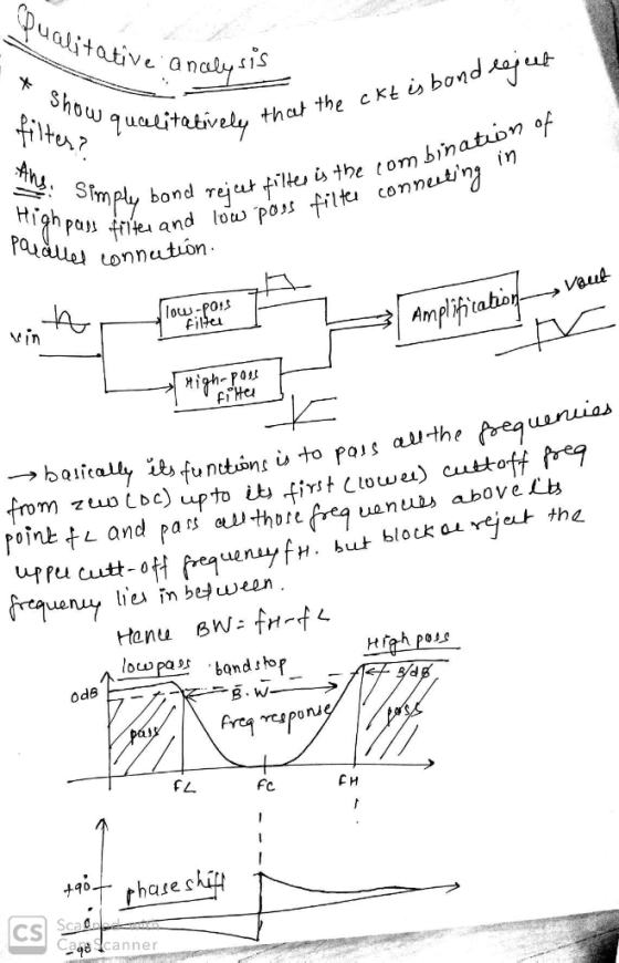
please help with the Theoretical Analysis and Designing the
Filter
EE213 Project Report Format Introduction Circuit...
Learning Goal: To analyze and design a passive, second-order bandpass filter using a series RLC circuit....
 Learning Goal: To analyze and design a passive, second-order bandpass filter using a series RLC circuit. A bandpass filter is needed for an equalizer, a device that allows one to select the level of amplification of sounds within a specific frequency band while not affecting the sounds outside that band. The filter should block frequencies lower than 1.8 kHz and have a resonant frequency of 5.4 kHz A 3.2 AF capacitor and any needed resistors and inductors are available to...
Learning Goal: To analyze and design a passive, first-order low-pass filter using a series RL circuit....
 Learning Goal: To analyze and design a passive, first-order low-pass filter using a series RL circuit. The analysis and design will be repeated for a series RC circuit. An electrocardiogram needs to detect periodic signals of approximately 1 Hz (since the resting heart rate of a healthy adult is between 55 and 70 beats per minute). The instrument operates in an electrical environment that is very noisy with a frequency of 60 Hz. It is desirable to have a low-pass...
Analysis and Design of Low Pass Filters 1 of 3 > Before designing the throne must...
 Analysis and Design of Low Pass Filters 1 of 3 > Before designing the throne must understand the relationship between the output voltage of the circut and the frequency. For a series RL crout, how do the impedances of the circut elements depend on the frequency? Select the correct answer View Available Hintſ Learning Goal: To analyze and design a passive, first-order low-pass filter using a series RL rout. The analysis and design will be repeated for a series RC...
Learning Goal: To analyze and design a passive, first-order low- pass filter using a series RL...
 Learning Goal: To analyze and design a passive, first-order low- pass filter using a series RL circuit. The analysis and design will be repeated for a series RC circuit. An electrocardiogram needs to detect periodic signals of approximately 1 Hz (since the resting heart rate of a healthy adult is between 55 and 70 beats per minute). The instrument operates in an electrical environment that is very noisy with a frequency of 60 Hz. It is desirable to have a...
Vout should be a sinusoid signal of 12Vp-p Dc voltage to uA741 : +/-8.5V Please simulate...
 Vout should be a sinusoid signal of 12Vp-p
Dc voltage to uA741 : +/-8.5V
Please simulate as well
please help, im completely lost on this
this is all of the information
Experiment 5. RC Sinusoidal Oscillators PURPOSE: This laboratory provides an introduction to the background, analysis and design of sinusoidal oscillators using RC feedback networks and active devices to achieve the criteria for continuous oscillations to occur. EQUIPMENT REQUIRED : 1 Operational amplifier u.A741 1 CEU development station Resistors and...
Vout should be a sinusoid signal of 12Vp-p
Dc voltage to uA741 : +/-8.5V
Please simulate as well
please help, im completely lost on this
this is all of the information
Experiment 5. RC Sinusoidal Oscillators PURPOSE: This laboratory provides an introduction to the background, analysis and design of sinusoidal oscillators using RC feedback networks and active devices to achieve the criteria for continuous oscillations to occur. EQUIPMENT REQUIRED : 1 Operational amplifier u.A741 1 CEU development station Resistors and...
 Learning Goal: To analyze and design a passive, second-order bandpass filter using a series RLC circuit. A bandpass filter is needed for an equalizer, a device that allows one to select the level of amplification of sounds within a specific frequency band while not affecting the sounds outside that band. The filter should block frequencies lower than 1.8 kHz and have a resonant frequency of 5.4 kHz A 3.2 AF capacitor and any needed resistors and inductors are available to...
 Learning Goal: To analyze and design a passive, first-order low-pass filter using a series RL circuit. The analysis and design will be repeated for a series RC circuit. An electrocardiogram needs to detect periodic signals of approximately 1 Hz (since the resting heart rate of a healthy adult is between 55 and 70 beats per minute). The instrument operates in an electrical environment that is very noisy with a frequency of 60 Hz. It is desirable to have a low-pass...
 Analysis and Design of Low Pass Filters 1 of 3 > Before designing the throne must understand the relationship between the output voltage of the circut and the frequency. For a series RL crout, how do the impedances of the circut elements depend on the frequency? Select the correct answer View Available Hintſ Learning Goal: To analyze and design a passive, first-order low-pass filter using a series RL rout. The analysis and design will be repeated for a series RC...
 Learning Goal: To analyze and design a passive, first-order low- pass filter using a series RL circuit. The analysis and design will be repeated for a series RC circuit. An electrocardiogram needs to detect periodic signals of approximately 1 Hz (since the resting heart rate of a healthy adult is between 55 and 70 beats per minute). The instrument operates in an electrical environment that is very noisy with a frequency of 60 Hz. It is desirable to have a...
 Vout should be a sinusoid signal of 12Vp-p
Dc voltage to uA741 : +/-8.5V
Please simulate as well
please help, im completely lost on this
this is all of the information
Experiment 5. RC Sinusoidal Oscillators PURPOSE: This laboratory provides an introduction to the background, analysis and design of sinusoidal oscillators using RC feedback networks and active devices to achieve the criteria for continuous oscillations to occur. EQUIPMENT REQUIRED : 1 Operational amplifier u.A741 1 CEU development station Resistors and...
Vout should be a sinusoid signal of 12Vp-p
Dc voltage to uA741 : +/-8.5V
Please simulate as well
please help, im completely lost on this
this is all of the information
Experiment 5. RC Sinusoidal Oscillators PURPOSE: This laboratory provides an introduction to the background, analysis and design of sinusoidal oscillators using RC feedback networks and active devices to achieve the criteria for continuous oscillations to occur. EQUIPMENT REQUIRED : 1 Operational amplifier u.A741 1 CEU development station Resistors and...
Most questions answered within 3 hours.
-
On a diagram with the interest rate on the vertical axis and the
quantity of money...
asked 38 seconds ago -
A sample containing 4.60 g of O2 gas has an initial volume of
19.0 L ....
asked 7 minutes ago -
What qualitative assay would you use to distinguish vanillin
from 5-bromovanillin and what would you expect...
asked 8 minutes ago -
ECS 3702
asked 8 minutes ago -
What kind of materials are found in Leviticus? Give a simple
description of this book. Also...
asked 1 hour ago -
17.1 Energy drink commercials. A study was designed to compare
Red Bull energy drink commercials. Each...
asked 1 hour ago -
The life that maximizes net present value and shareholder wealth
is known as...
Physical Life
Economic...
asked 1 hour ago -
You have to write your code in C++ (as a cpp file) and prepare a
docx...
asked 2 hours ago -
Why does the spectrum of bromocresol green changes at different
pHs? What causes the change?
asked 2 hours ago -
Rice Company has a unit selling price of $690, variable costs
per unit of $390, and...
asked 3 hours ago -
The DeVille Company reported pretax accounting
income on its income statement as follows:
2018
$
425,000...
asked 3 hours ago -
Argue for or against the "Three Strikes"laws. Provide a rationale
to support your response.
asked 4 hours ago