
Homework Answers
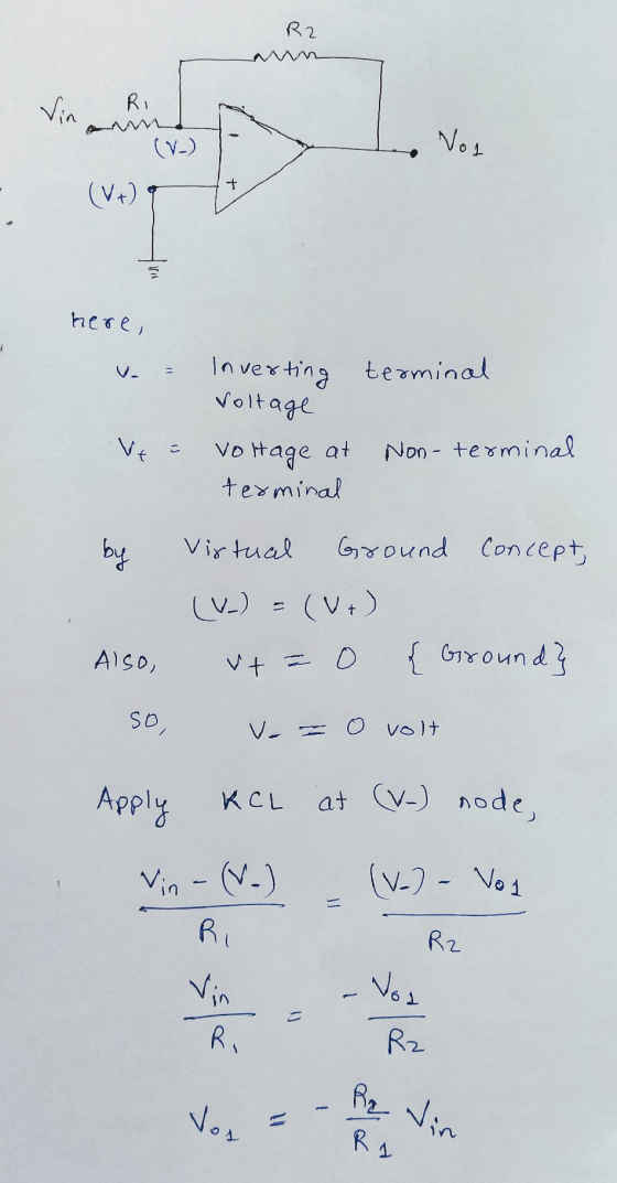
Here , both opamp is negative feedback so we can apply virtual ground concept by which voltage at the inverting terminal becomes equal to the voltage at the non inverting terminal.
For calculating Vo we have to calculate the output of each opamp seperately.


Add Answer to:
1) For the bridge opamp circuit in the figure, find the total voltage gain expression Vo/Vin...
Part 1: Gain =8, R1=5k, R2=20k, R5=100, and V1=1V. Find Vout/Vin. Part 2: Let R4=0 and...
 Part 1: Gain =8, R1=5k, R2=20k, R5=100, and V1=1V. Find
Vout/Vin.
Part 2: Let R4=0 and R3=∞. Find Vout/Vin. (Hint: make sure the
button called Enable Biased Voltage
Display is depressed) (Another Hint: when a resistance is zero,
short it; when a resistance is
infinity, delete it).
Part 3: Let R4=2k and R3=∞. Find Vout/Vin.
Part 4: Let R4=0 and R3=1000. Find Vout/Vin.
Part 5:Let R4=2k and R3=1000. Find Vout/Vin.
R1 Vout G1 5k R4 1k R5 100 V1 R2...
Part 1: Gain =8, R1=5k, R2=20k, R5=100, and V1=1V. Find
Vout/Vin.
Part 2: Let R4=0 and R3=∞. Find Vout/Vin. (Hint: make sure the
button called Enable Biased Voltage
Display is depressed) (Another Hint: when a resistance is zero,
short it; when a resistance is
infinity, delete it).
Part 3: Let R4=2k and R3=∞. Find Vout/Vin.
Part 4: Let R4=0 and R3=1000. Find Vout/Vin.
Part 5:Let R4=2k and R3=1000. Find Vout/Vin.
R1 Vout G1 5k R4 1k R5 100 V1 R2...
Find the voltage gain vO and the current iL for the difference amplifier for the case...
 Find the voltage gain vO and the current iL for the difference
amplifier for the case R1 = 10k, R2 = 100k, R3 = 5k and RL = 2.5k.
look 2.5K SRL 5K R3 0.31
Find the voltage gain vO and the current iL for the difference
amplifier for the case R1 = 10k, R2 = 100k, R3 = 5k and RL = 2.5k.
look 2.5K SRL 5K R3 0.31
Find the output voltage Vo as an expression in terms of the input sources Vi, v2,...
 Find the output voltage Vo as an expression in terms of the input sources Vi, v2, v3, and the resistance R in the following op-amp circuit. 3. Ri Vy R: 4. In the following two stage op-amp circuit, find the output voltage Vo as an expression in terms of the input voltages v1, v2 and resistor values R1, R2, R3, and R4. R2 R ウー+
Vdd RL VO OL vin Rg ww The figure shows the circuit diagram of a common...
 Vdd RL VO OL vin Rg ww The figure shows the circuit diagram of a common source amplifier using a JFET supplied by an ideal sinusoidal signal source vin of variable frequency. The values of the circuit components are given as follows; Rg = 560k, RL = 1.5k, ro = infinity, C = 0.01 microfarads, gm = 7.0mA/Volt. At a frequency of 50 Hz it is determined that the magnitude of the gain vo/vin is nearest to which of the...
Assuming an ideal op-amp in the following circuit, find output voltage, Vo if R1= 2 K2,...
 Assuming an ideal op-amp in the following circuit, find output voltage, Vo if R1= 2 K2, R2=8 K2, R3=5.1 K2, R4=6 KN, R5=14 KN, R6=4.2 KS, RL=10.3 KS, V1=1V, 12=0.5 mA and V3=3.2 V. R6 R1 R5 Vo w + * RL + 12 R2 V1 R3 R4 V3 Answer: OV Using the above circuit, but consider the following component values: R1= 2 K12 R2=8 K2, R3=2.9 K2, R4=6 KI2, R5=10.8 K92, R6=15 KO, RL=10 K2, V1=1V, 12=0.5mA and V3=2V....
Assuming an ideal op-amp in the following circuit, find output voltage, Vo if R1= 2 K12,...
 Assuming an ideal op-amp in the following circuit, find output voltage, Vo if R1= 2 K12, R2=8 KN, R3=3.9 KN, R4=6 KN, R5=18 K2, R6=4.4 KN, RL=12.5 KN, V1=1V, 12=0.5 mA and V3=3.4 V. R6 R1 R5 Vo + + RL R2 V1 R3 R4 + V3 Answer: LOV Using the above circuit, but consider the following component values: R1= 2 KO2 R2=8 K12, R3=3.6 K12, R4=6 K12, R5=16.9 KN, R6=15 KN, RL=10 KO, V1=1V, 12=0.5mA and V3=2V. What is...
Assuming an ideal op-amp in the following circuit, find output voltage, Vo if R1= 2 K2,...
 Assuming an ideal op-amp in the following circuit, find output voltage, Vo if R1= 2 K2, R2=8 K12, R3=3.8 KS2, R4=6 KI2, R5=15 KS2, R6=3.8 KN, RL=9.8 K12, V1=1V, 12=0.5 mA and V3=2.2 V. } R6 R1 w R5 w + Vo + } RL 12 R2 V1 R3 R4 + +1 V3 Using the above circuit, but consider the following component values: R1= 2 KN R2=8 K2, R3=4.1 K12, R4=6 KI2, R5=17.0 K12, R6=15 KI, RL=10 KI, V1=1V, 12=0.5mA...
For the amplifier circuits in Figs.3 and 7: a. Write an expression for the output voltage,...
 For the amplifier circuits in Figs.3 and 7:
a. Write an expression for the output voltage, vo, in terms of
the resistor symbols and the input voltage, vin.
---For the first circuit (Fig. 3), the feedback resistor is the
series combination of R2 and R3. Use both of these resistor symbols
in your expression.
-- For circuit 2 (Fig. 7), assume that vin = 5V and ignore
potentiometer R1 and C3.
b. Using resistor values and input voltage amplitudes, calculate...
For the amplifier circuits in Figs.3 and 7:
a. Write an expression for the output voltage, vo, in terms of
the resistor symbols and the input voltage, vin.
---For the first circuit (Fig. 3), the feedback resistor is the
series combination of R2 and R3. Use both of these resistor symbols
in your expression.
-- For circuit 2 (Fig. 7), assume that vin = 5V and ignore
potentiometer R1 and C3.
b. Using resistor values and input voltage amplitudes, calculate...
R2 R1 1,C2 C1 Vo vin + The figure shows the circuit diagram of an active...
 R2 R1 1,C2 C1 Vo vin + The figure shows the circuit diagram of an active filter using an ideal operational amplifier. The values of the circuit components are as follows, R1 - 960 ohms, R2 - 2600 ohms, C1 - 1.0 microfarads, C2-0.8 microfarads. The magnitude of the circuit gain vo/vin at a frequency of 200Hz is determined as nearest to which of the following answers:- 00 O 0.7 O 1.5 22 3.3
Please answer clearly Question 2 The amplifier shown in Figure 2 has the following parameters: Kn(W/L)-1 mA/V2, V-1 V Determine a) Voltage gain (Vo/vi) b) Input resistance (R) c) Output resistance (R...
 Please answer clearly
Question 2 The amplifier shown in Figure 2 has the following parameters: Kn(W/L)-1 mA/V2, V-1 V Determine a) Voltage gain (Vo/vi) b) Input resistance (R) c) Output resistance (Ro) d) Maximum output voltage swing so as the amplifier stays in saturation mode. Assume VDD-20 V, R1-2.5 ΚΩ, R2-1KQ, R3-0.5 ΚΩ, R4-5 MQ, R5_1ΜΩ. R4 R1 R5 R2 Ro R3
Question 2 The amplifier shown in Figure 2 has the following parameters: Kn(W/L)-1 mA/V2, V-1 V Determine a)...
Please answer clearly
Question 2 The amplifier shown in Figure 2 has the following parameters: Kn(W/L)-1 mA/V2, V-1 V Determine a) Voltage gain (Vo/vi) b) Input resistance (R) c) Output resistance (Ro) d) Maximum output voltage swing so as the amplifier stays in saturation mode. Assume VDD-20 V, R1-2.5 ΚΩ, R2-1KQ, R3-0.5 ΚΩ, R4-5 MQ, R5_1ΜΩ. R4 R1 R5 R2 Ro R3
Question 2 The amplifier shown in Figure 2 has the following parameters: Kn(W/L)-1 mA/V2, V-1 V Determine a)...
 Part 1: Gain =8, R1=5k, R2=20k, R5=100, and V1=1V. Find
Vout/Vin.
Part 2: Let R4=0 and R3=∞. Find Vout/Vin. (Hint: make sure the
button called Enable Biased Voltage
Display is depressed) (Another Hint: when a resistance is zero,
short it; when a resistance is
infinity, delete it).
Part 3: Let R4=2k and R3=∞. Find Vout/Vin.
Part 4: Let R4=0 and R3=1000. Find Vout/Vin.
Part 5:Let R4=2k and R3=1000. Find Vout/Vin.
R1 Vout G1 5k R4 1k R5 100 V1 R2...
Part 1: Gain =8, R1=5k, R2=20k, R5=100, and V1=1V. Find
Vout/Vin.
Part 2: Let R4=0 and R3=∞. Find Vout/Vin. (Hint: make sure the
button called Enable Biased Voltage
Display is depressed) (Another Hint: when a resistance is zero,
short it; when a resistance is
infinity, delete it).
Part 3: Let R4=2k and R3=∞. Find Vout/Vin.
Part 4: Let R4=0 and R3=1000. Find Vout/Vin.
Part 5:Let R4=2k and R3=1000. Find Vout/Vin.
R1 Vout G1 5k R4 1k R5 100 V1 R2...
 Find the voltage gain vO and the current iL for the difference
amplifier for the case R1 = 10k, R2 = 100k, R3 = 5k and RL = 2.5k.
look 2.5K SRL 5K R3 0.31
Find the voltage gain vO and the current iL for the difference
amplifier for the case R1 = 10k, R2 = 100k, R3 = 5k and RL = 2.5k.
look 2.5K SRL 5K R3 0.31
 Find the output voltage Vo as an expression in terms of the input sources Vi, v2, v3, and the resistance R in the following op-amp circuit. 3. Ri Vy R: 4. In the following two stage op-amp circuit, find the output voltage Vo as an expression in terms of the input voltages v1, v2 and resistor values R1, R2, R3, and R4. R2 R ウー+
 Vdd RL VO OL vin Rg ww The figure shows the circuit diagram of a common source amplifier using a JFET supplied by an ideal sinusoidal signal source vin of variable frequency. The values of the circuit components are given as follows; Rg = 560k, RL = 1.5k, ro = infinity, C = 0.01 microfarads, gm = 7.0mA/Volt. At a frequency of 50 Hz it is determined that the magnitude of the gain vo/vin is nearest to which of the...
 Assuming an ideal op-amp in the following circuit, find output voltage, Vo if R1= 2 K2, R2=8 K2, R3=5.1 K2, R4=6 KN, R5=14 KN, R6=4.2 KS, RL=10.3 KS, V1=1V, 12=0.5 mA and V3=3.2 V. R6 R1 R5 Vo w + * RL + 12 R2 V1 R3 R4 V3 Answer: OV Using the above circuit, but consider the following component values: R1= 2 K12 R2=8 K2, R3=2.9 K2, R4=6 KI2, R5=10.8 K92, R6=15 KO, RL=10 K2, V1=1V, 12=0.5mA and V3=2V....
 Assuming an ideal op-amp in the following circuit, find output voltage, Vo if R1= 2 K12, R2=8 KN, R3=3.9 KN, R4=6 KN, R5=18 K2, R6=4.4 KN, RL=12.5 KN, V1=1V, 12=0.5 mA and V3=3.4 V. R6 R1 R5 Vo + + RL R2 V1 R3 R4 + V3 Answer: LOV Using the above circuit, but consider the following component values: R1= 2 KO2 R2=8 K12, R3=3.6 K12, R4=6 K12, R5=16.9 KN, R6=15 KN, RL=10 KO, V1=1V, 12=0.5mA and V3=2V. What is...
 Assuming an ideal op-amp in the following circuit, find output voltage, Vo if R1= 2 K2, R2=8 K12, R3=3.8 KS2, R4=6 KI2, R5=15 KS2, R6=3.8 KN, RL=9.8 K12, V1=1V, 12=0.5 mA and V3=2.2 V. } R6 R1 w R5 w + Vo + } RL 12 R2 V1 R3 R4 + +1 V3 Using the above circuit, but consider the following component values: R1= 2 KN R2=8 K2, R3=4.1 K12, R4=6 KI2, R5=17.0 K12, R6=15 KI, RL=10 KI, V1=1V, 12=0.5mA...
 For the amplifier circuits in Figs.3 and 7:
a. Write an expression for the output voltage, vo, in terms of
the resistor symbols and the input voltage, vin.
---For the first circuit (Fig. 3), the feedback resistor is the
series combination of R2 and R3. Use both of these resistor symbols
in your expression.
-- For circuit 2 (Fig. 7), assume that vin = 5V and ignore
potentiometer R1 and C3.
b. Using resistor values and input voltage amplitudes, calculate...
For the amplifier circuits in Figs.3 and 7:
a. Write an expression for the output voltage, vo, in terms of
the resistor symbols and the input voltage, vin.
---For the first circuit (Fig. 3), the feedback resistor is the
series combination of R2 and R3. Use both of these resistor symbols
in your expression.
-- For circuit 2 (Fig. 7), assume that vin = 5V and ignore
potentiometer R1 and C3.
b. Using resistor values and input voltage amplitudes, calculate...
 R2 R1 1,C2 C1 Vo vin + The figure shows the circuit diagram of an active filter using an ideal operational amplifier. The values of the circuit components are as follows, R1 - 960 ohms, R2 - 2600 ohms, C1 - 1.0 microfarads, C2-0.8 microfarads. The magnitude of the circuit gain vo/vin at a frequency of 200Hz is determined as nearest to which of the following answers:- 00 O 0.7 O 1.5 22 3.3
 Please answer clearly
Question 2 The amplifier shown in Figure 2 has the following parameters: Kn(W/L)-1 mA/V2, V-1 V Determine a) Voltage gain (Vo/vi) b) Input resistance (R) c) Output resistance (Ro) d) Maximum output voltage swing so as the amplifier stays in saturation mode. Assume VDD-20 V, R1-2.5 ΚΩ, R2-1KQ, R3-0.5 ΚΩ, R4-5 MQ, R5_1ΜΩ. R4 R1 R5 R2 Ro R3
Question 2 The amplifier shown in Figure 2 has the following parameters: Kn(W/L)-1 mA/V2, V-1 V Determine a)...
Please answer clearly
Question 2 The amplifier shown in Figure 2 has the following parameters: Kn(W/L)-1 mA/V2, V-1 V Determine a) Voltage gain (Vo/vi) b) Input resistance (R) c) Output resistance (Ro) d) Maximum output voltage swing so as the amplifier stays in saturation mode. Assume VDD-20 V, R1-2.5 ΚΩ, R2-1KQ, R3-0.5 ΚΩ, R4-5 MQ, R5_1ΜΩ. R4 R1 R5 R2 Ro R3
Question 2 The amplifier shown in Figure 2 has the following parameters: Kn(W/L)-1 mA/V2, V-1 V Determine a)...
Most questions answered within 3 hours.
-
A marketing executive who knowingly authorizes a shoddy
defective product to be brought to market is...
asked 1 minute ago -
Write a psudocode:
1. Define a function called authorize that takes in 2 strings,
uName, and...
asked 5 minutes ago -
What Hall voltage (in mV) is produced by a 0.180 T field applied
across a 2.60...
asked 4 minutes ago -
What mass of ethylene glycol (C2H6O2) must be added to 211.0 g
of water to obtain...
asked 7 minutes ago -
Mary's employer has a defined benefits retirement plan, which
pay 3.2% of her last year's salary...
asked 10 minutes ago -
What are the characteristics and behavior of an ethical
manager?
Explain, in your words, what ethics...
asked 27 minutes ago -
1. Which of the following is NOT an argument that McMahan uses
to show that jus...
asked 48 minutes ago -
A crate slides up a frictionless slope. At the end of 3 seconds
its velocity is...
asked 1 hour ago -
Use the following information to answer the next seven
questions.
Suppose there are three potential states...
asked 1 hour ago -
If we only have interstitial and substitutional diffusion, then
what do we consider the process of...
asked 1 hour ago -
You look at yourself in a shiny 9.6-cm-diameter Christmas tree
ball.
If your face is 21.0...
asked 1 hour ago -
If we were to measure the relaxation time of a muscle after
undergoing tetanus compared to...
asked 1 hour ago