
Homework Answers

Add Answer to:
Problem 1. (40 pts) Here is a design for a beam as shown in Figs Check...
M 3: (20 points) Design the stirrup spacing for the beam shown below. Change your design between ...
 m 3: (20 points) Design the stirrup spacing for the beam shown below. Change your design between Zones 1, 2, and 3 of the beam length, using a uniform spacing in each zone. Ignore the self-weight of the beam. Loads on the beam are service loads so load factors must be applied according to ACI 318 (subscripts "d" and T" denote dead and live loads, respectively). Material strengths are fe 4,0oo psi and fy 60,000 psi. The total factored shear...
A section for a NWC beam is shown below. Your task is to work on the...
 A section for a NWC beam is shown below. Your task is to work on the shear design of this beam. Assume fc=4000psi; fy=60ksi. Use No 3 Grade double-leg stirrup, yield strength of stirrups=fys = 60 ksi. in. stirrups 21 in. 12 in 4) Assuming low shear stresses, (i.e., Vs<41fc bw d), the maximum stirrup spacing based on beam depth is: A. 24 -in B. 12.5-in C. 6.25-in D. 12-in 5) If Vc = 37.9 kip and Vu= 73 kip,...
The beam shown below is subjected to a uniformly distributed load, w, over its entire length....
 The beam shown below is subjected to a uniformly distributed
load, w, over its entire length. What is the largest value of w
that the beam can withstand prior to collapse? For simplicity, you
may assume that w includes the weight of the beam itself.
Use ACI 318-14 building code requirements for structural
concrete
The beam shown below is subjected to a uniformly distributed load, w, over its entire length. What is the largest value of w that the beam...
The beam shown below is subjected to a uniformly distributed
load, w, over its entire length. What is the largest value of w
that the beam can withstand prior to collapse? For simplicity, you
may assume that w includes the weight of the beam itself.
Use ACI 318-14 building code requirements for structural
concrete
The beam shown below is subjected to a uniformly distributed load, w, over its entire length. What is the largest value of w that the beam...
Show Diagrams Case 2: Design of Short Columns - Small Eccentricity Determine whether the spiral column of cross section shown in Figure 2.1 is adequate to carry a factored axial load Pu of 540 kips. A...
 Show Diagrams
Case 2: Design of Short Columns - Small Eccentricity Determine whether the spiral column of cross section shown in Figure 2.1 is adequate to carry a factored axial load Pu of 540 kips. Assume small eccentricity. Check the spiral. Use fc 4000 psi and fy -60,000 psi. 큠.φ @ 2 7-'8 bars 1cover Figure 2.1 Spiral Column
Case 2: Design of Short Columns - Small Eccentricity Determine whether the spiral column of cross section shown in Figure 2.1...
Show Diagrams
Case 2: Design of Short Columns - Small Eccentricity Determine whether the spiral column of cross section shown in Figure 2.1 is adequate to carry a factored axial load Pu of 540 kips. Assume small eccentricity. Check the spiral. Use fc 4000 psi and fy -60,000 psi. 큠.φ @ 2 7-'8 bars 1cover Figure 2.1 Spiral Column
Case 2: Design of Short Columns - Small Eccentricity Determine whether the spiral column of cross section shown in Figure 2.1...
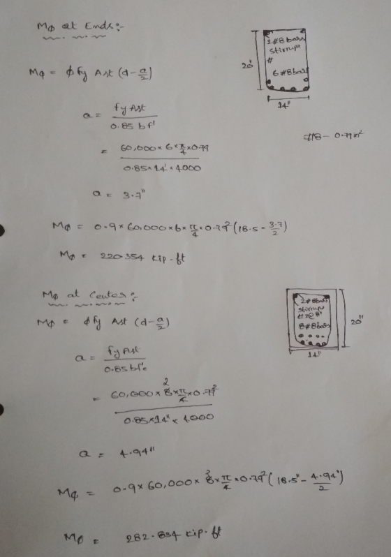
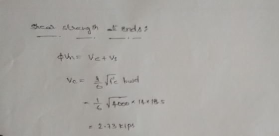
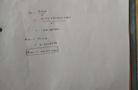
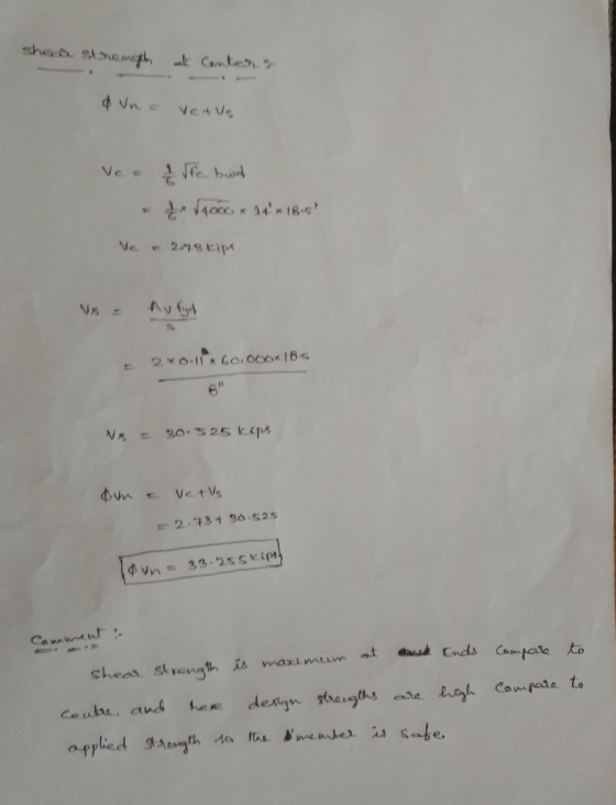
Compute the design strength(positive moment), фМ., for the beam shown below. note that the beam shown...
 Compute the design strength(positive moment), фМ., for the beam shown below. note that the beam shown is an independent beam, which does not bend in conjunction with any adjacent beam(s). The material strengths are as follows: Please l. f, - 60,000 psi 3,000 psi (30 pts.) Check the development length for the bar size shown (No. 8 bars). The bars are not epoxy coated and the concrete is normalweight concrete. Assume the simplified equation can be used. The bars are...
Name: Total__/25 Follow ACI 318-19 to answer the following questions: Problem #1 (6 points) Determine the...
 Name: Total__/25 Follow ACI 318-19 to answer the following questions: Problem #1 (6 points) Determine the following for the beam cross section shown below. Assume f = 4,500 psi, fy = 60,000 psi . Clear cover =1.5 in. Bars are coated b #4 stirrups h d ::: 25 in 2.5 in Cross section b=14 in h=18 in d = 14.75 in As = 3.6 in ( 67) Ye Co= K,= 1 (The required development length of the tension bars) =...
LECTURE # 1) beft 36 " Determine the design moment strength of the section shown. Use...
 LECTURE # 1) beft 36 " Determine the design moment strength of the section shown. Use fc' = 4 ksi and fy = 60 ksi. (10 | Also check the minimum reinforcement 32 requirement and the ductility of the beam. 8-# 9 bars 14in Asyrin Pin= 200 156 As OK TAs fy =480 Ksi OXS f 4.3530
LECTURE # 1) beft 36 " Determine the design moment strength of the section shown. Use fc' = 4 ksi and fy =...
LECTURE # 1) beft 36 " Determine the design moment strength of the section shown. Use fc' = 4 ksi and fy = 60 ksi. (10 | Also check the minimum reinforcement 32 requirement and the ductility of the beam. 8-# 9 bars 14in Asyrin Pin= 200 156 As OK TAs fy =480 Ksi OXS f 4.3530
LECTURE # 1) beft 36 " Determine the design moment strength of the section shown. Use fc' = 4 ksi and fy =...
The T-beam shown in Figure 1 supports the un-factored dead load of 1.4 kips/ft and live...
 The T-beam shown in Figure 1 supports the un-factored dead load
of 1.4 kips/ft and live load of 1.5 kips/ft. The dead load does not
include the self-weight of the beam. The material properties are as
follows: fc’=3000 psi; fy=60,000 psi. Design the shear
reinforcement (stirrups). Plot the stirrups distribution along the
span of the beam.
DL= 1.4 kips/ft ; L2=1.5 kips/Ft * 75 Sz=7 X * b=3616. hr-6in k ) انا امه hw-lain + * bw=12 in
The T-beam shown in Figure 1 supports the un-factored dead load
of 1.4 kips/ft and live load of 1.5 kips/ft. The dead load does not
include the self-weight of the beam. The material properties are as
follows: fc’=3000 psi; fy=60,000 psi. Design the shear
reinforcement (stirrups). Plot the stirrups distribution along the
span of the beam.
DL= 1.4 kips/ft ; L2=1.5 kips/Ft * 75 Sz=7 X * b=3616. hr-6in k ) انا امه hw-lain + * bw=12 in
. Deisgn a reinforced concrete cross-section with unknown dimensions Problem 1 Design the steel reinforcement for...
 . Deisgn a reinforced concrete cross-section with unknown dimensions Problem 1 Design the steel reinforcement for the beam shown in Figure 1 that supports its own self-weight, a uninformly distributed dead load, a uniformly distributed live load, and a live point load located at midspan. In your solution, you should select the area of reinforcement, the number and size of reinforcing bars, and the section depth in order to receive full credit. Assume J 5,000 psi, fy 60,000 psi. 16...
1. A rectangular beam with b 16 in., d-17 in., and h 20 in. has a clear span of 24 ft. as shown b...
 1. A rectangular beam with b 16 in., d-17 in., and h 20 in. has a clear span of 24 ft. as shown below. The beam has 1 ft. of bearing at each end, so for analysis purposes it is treated as a 25 ft. simple span (to center of bearing at each end). The beam supports an unfactored concentrated live load of P-65 kips. The beam is reinforced with 6-#10 longitudinal bars and #4 stirrups. Material strengths are fc-4,000,...
 m 3: (20 points) Design the stirrup spacing for the beam shown below. Change your design between Zones 1, 2, and 3 of the beam length, using a uniform spacing in each zone. Ignore the self-weight of the beam. Loads on the beam are service loads so load factors must be applied according to ACI 318 (subscripts "d" and T" denote dead and live loads, respectively). Material strengths are fe 4,0oo psi and fy 60,000 psi. The total factored shear...
 A section for a NWC beam is shown below. Your task is to work on the shear design of this beam. Assume fc=4000psi; fy=60ksi. Use No 3 Grade double-leg stirrup, yield strength of stirrups=fys = 60 ksi. in. stirrups 21 in. 12 in 4) Assuming low shear stresses, (i.e., Vs<41fc bw d), the maximum stirrup spacing based on beam depth is: A. 24 -in B. 12.5-in C. 6.25-in D. 12-in 5) If Vc = 37.9 kip and Vu= 73 kip,...
 The beam shown below is subjected to a uniformly distributed
load, w, over its entire length. What is the largest value of w
that the beam can withstand prior to collapse? For simplicity, you
may assume that w includes the weight of the beam itself.
Use ACI 318-14 building code requirements for structural
concrete
The beam shown below is subjected to a uniformly distributed load, w, over its entire length. What is the largest value of w that the beam...
The beam shown below is subjected to a uniformly distributed
load, w, over its entire length. What is the largest value of w
that the beam can withstand prior to collapse? For simplicity, you
may assume that w includes the weight of the beam itself.
Use ACI 318-14 building code requirements for structural
concrete
The beam shown below is subjected to a uniformly distributed load, w, over its entire length. What is the largest value of w that the beam...
 Show Diagrams
Case 2: Design of Short Columns - Small Eccentricity Determine whether the spiral column of cross section shown in Figure 2.1 is adequate to carry a factored axial load Pu of 540 kips. Assume small eccentricity. Check the spiral. Use fc 4000 psi and fy -60,000 psi. 큠.φ @ 2 7-'8 bars 1cover Figure 2.1 Spiral Column
Case 2: Design of Short Columns - Small Eccentricity Determine whether the spiral column of cross section shown in Figure 2.1...
Show Diagrams
Case 2: Design of Short Columns - Small Eccentricity Determine whether the spiral column of cross section shown in Figure 2.1 is adequate to carry a factored axial load Pu of 540 kips. Assume small eccentricity. Check the spiral. Use fc 4000 psi and fy -60,000 psi. 큠.φ @ 2 7-'8 bars 1cover Figure 2.1 Spiral Column
Case 2: Design of Short Columns - Small Eccentricity Determine whether the spiral column of cross section shown in Figure 2.1...
 Compute the design strength(positive moment), фМ., for the beam shown below. note that the beam shown is an independent beam, which does not bend in conjunction with any adjacent beam(s). The material strengths are as follows: Please l. f, - 60,000 psi 3,000 psi (30 pts.) Check the development length for the bar size shown (No. 8 bars). The bars are not epoxy coated and the concrete is normalweight concrete. Assume the simplified equation can be used. The bars are...
 Name: Total__/25 Follow ACI 318-19 to answer the following questions: Problem #1 (6 points) Determine the following for the beam cross section shown below. Assume f = 4,500 psi, fy = 60,000 psi . Clear cover =1.5 in. Bars are coated b #4 stirrups h d ::: 25 in 2.5 in Cross section b=14 in h=18 in d = 14.75 in As = 3.6 in ( 67) Ye Co= K,= 1 (The required development length of the tension bars) =...
 LECTURE # 1) beft 36 " Determine the design moment strength of the section shown. Use fc' = 4 ksi and fy = 60 ksi. (10 | Also check the minimum reinforcement 32 requirement and the ductility of the beam. 8-# 9 bars 14in Asyrin Pin= 200 156 As OK TAs fy =480 Ksi OXS f 4.3530
LECTURE # 1) beft 36 " Determine the design moment strength of the section shown. Use fc' = 4 ksi and fy =...
LECTURE # 1) beft 36 " Determine the design moment strength of the section shown. Use fc' = 4 ksi and fy = 60 ksi. (10 | Also check the minimum reinforcement 32 requirement and the ductility of the beam. 8-# 9 bars 14in Asyrin Pin= 200 156 As OK TAs fy =480 Ksi OXS f 4.3530
LECTURE # 1) beft 36 " Determine the design moment strength of the section shown. Use fc' = 4 ksi and fy =...
 The T-beam shown in Figure 1 supports the un-factored dead load
of 1.4 kips/ft and live load of 1.5 kips/ft. The dead load does not
include the self-weight of the beam. The material properties are as
follows: fc’=3000 psi; fy=60,000 psi. Design the shear
reinforcement (stirrups). Plot the stirrups distribution along the
span of the beam.
DL= 1.4 kips/ft ; L2=1.5 kips/Ft * 75 Sz=7 X * b=3616. hr-6in k ) انا امه hw-lain + * bw=12 in
The T-beam shown in Figure 1 supports the un-factored dead load
of 1.4 kips/ft and live load of 1.5 kips/ft. The dead load does not
include the self-weight of the beam. The material properties are as
follows: fc’=3000 psi; fy=60,000 psi. Design the shear
reinforcement (stirrups). Plot the stirrups distribution along the
span of the beam.
DL= 1.4 kips/ft ; L2=1.5 kips/Ft * 75 Sz=7 X * b=3616. hr-6in k ) انا امه hw-lain + * bw=12 in
 . Deisgn a reinforced concrete cross-section with unknown dimensions Problem 1 Design the steel reinforcement for the beam shown in Figure 1 that supports its own self-weight, a uninformly distributed dead load, a uniformly distributed live load, and a live point load located at midspan. In your solution, you should select the area of reinforcement, the number and size of reinforcing bars, and the section depth in order to receive full credit. Assume J 5,000 psi, fy 60,000 psi. 16...
 1. A rectangular beam with b 16 in., d-17 in., and h 20 in. has a clear span of 24 ft. as shown below. The beam has 1 ft. of bearing at each end, so for analysis purposes it is treated as a 25 ft. simple span (to center of bearing at each end). The beam supports an unfactored concentrated live load of P-65 kips. The beam is reinforced with 6-#10 longitudinal bars and #4 stirrups. Material strengths are fc-4,000,...
Most questions answered within 3 hours.
-
How do ECM Solutions assist in embedding a culture of continuous
improvement in an organization? (Project...
asked 12 minutes ago -
Directions
These directions introduce the idea of Essential Questions.
Since this may be a new concept...
asked 15 minutes ago -
1.b. Fiscal policy is said to suffer from ‘crowding out’.
Explain what this means and why...
asked 32 minutes ago -
The equation for the reaction of nitrogen and oxygen to form
nitrogen oxide is written as...
asked 36 minutes ago -
A scientist reproducing some photoelectric effect experiments
shines a light on a metal electrode, but doesn't...
asked 39 minutes ago -
In a study designed to test the effectiveness of magnets for
treating back pain, 35 patients...
asked 59 minutes ago -
Here are summary statistics for randomly selected weights of
newborn girls:
nequals=193,
x overbarxequals=30.5
hg,
sequals=7.3...
asked 49 minutes ago -
Exercise #3:
Create the “MathTest” class. It will have two class variables:
1) a question and...
asked 52 minutes ago -
In epidemiology, how do you calculate the overall incidence of
cure within two groups? What formula...
asked 55 minutes ago -
A 1 liter solution contains 0.357 M ammonium chloride and 0.268
M ammonia. Addition of 0.295...
asked 56 minutes ago -
What are the advantages and disadvantages of using virtual
reality simulations in health care education?
asked 1 hour ago -
Given input { 66, 28, 43, 29, 44, 69, 19 } and a hash function
h(x)...
asked 1 hour ago