
Homework Answers


Add Answer to:
1) (10 marks) In this question, you will calculate the voltages, currents and powers as follows...
1) (10 marks) In this question, you will calculate the voltages, currents and powers as follows...
 1) (10 marks) In this question, you will calculate the voltages, currents and powers as follows for the dc circuit in Fig. 1. a) Using the bottom node as the reference, calculate using node analysis, the other two node voltages. Label these other two node voltages in order from the top va and Vp. b) Calculate the current in each resistor. Calculate the power that is absorbed or produced by the each of the circuit elements. For each circuit element...
1. (12 marks) For the circuit in Fig. 1: a) Label all the node voltages and...
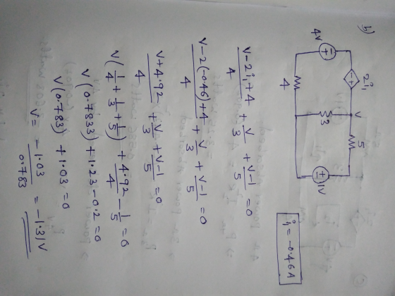
 1. (12 marks) For the circuit in Fig. 1: a) Label all the node voltages and show and label all branch currents for mesh analysis if they are not already labelled. (2 marks) b) Calculate the currents using mesh analysis. Show your equations and solutions in a logical order. (6 marks) c) Calculate the power generated or absorbed by each element including the sources. Show that power is conserved in the circuit. (4 marks) 10 12 212 512 1 341...
Review | Constants The source voltages vgi and vg2 in the circuit in (Figure 1) are...
 Review | Constants The source voltages vgi and vg2 in the circuit in (Figure 1) are 12 V and 8 V, respectively Figure 1 of 1 2i 81 8i +82 Find the total power absorbed in the circuit. Express your answer using three significant figures and include the appropriate units. View Available Hint(s) Hint 1. How to determine the power absorbed Determine the currents and voltage drops for all of the circuit elements, and calculate the power associated with each...
Solve this circuit using node-voltage method. Determine the currents through all the elements and voltages across...
 Solve this circuit using node-voltage method. Determine the
currents through all the elements and voltages across all elements.
Verify that the total power developed equals the total power
absorbed
Without repeating the node-voltage analysis, predict the node
voltages at nodes d, c, b and g, if node a was selected as the
reference node (or ground).
R2 560 n R, 1 kn R 430 Vs a ww R 820 n ww R3 2.2 kn V6R430 R, 1.5 k Rs 820...
Solve this circuit using node-voltage method. Determine the
currents through all the elements and voltages across all elements.
Verify that the total power developed equals the total power
absorbed
Without repeating the node-voltage analysis, predict the node
voltages at nodes d, c, b and g, if node a was selected as the
reference node (or ground).
R2 560 n R, 1 kn R 430 Vs a ww R 820 n ww R3 2.2 kn V6R430 R, 1.5 k Rs 820...
1. calculate node voltage V1 and V2 2. calculate the voltage drop across 10k resistor equal...
 1. calculate node voltage V1 and V2
2. calculate the voltage drop across 10k resistor equal to the
difference between V2 and Vs2
3. Calculate mesh current i1,i2, i3
4. calculate the current through 2.7k resistor
5. does the current measured through 2.7k resistor equal to the
difference between the currents i2 and i3? show all
calculations
equired Itheory a Construct the circuit shown in Fig. 2 on your breadboard. 1 k 2 w V, 1k22 V, 10 k92 VS2...
1. calculate node voltage V1 and V2
2. calculate the voltage drop across 10k resistor equal to the
difference between V2 and Vs2
3. Calculate mesh current i1,i2, i3
4. calculate the current through 2.7k resistor
5. does the current measured through 2.7k resistor equal to the
difference between the currents i2 and i3? show all
calculations
equired Itheory a Construct the circuit shown in Fig. 2 on your breadboard. 1 k 2 w V, 1k22 V, 10 k92 VS2...
Use measured resistance values and node analysis to calculate the node voltages. Use measured resistance values...
 Use measured resistance values and node analysis to calculate
the node voltages.
Use measured resistance values and mesh analysis to calculate
the mesh currents.
Show that the calculated values agree with the measured values
and explain any discrepancies between measured and calculated
values.
Introduction: In this pre-lab we will look at node voltages, mesh currents and bridge circuits. Bridge Circuits are used to make precision measurements, and in this lab -- -0 V2 will look at a DC Bridge Circuit...
Use measured resistance values and node analysis to calculate
the node voltages.
Use measured resistance values and mesh analysis to calculate
the mesh currents.
Show that the calculated values agree with the measured values
and explain any discrepancies between measured and calculated
values.
Introduction: In this pre-lab we will look at node voltages, mesh currents and bridge circuits. Bridge Circuits are used to make precision measurements, and in this lab -- -0 V2 will look at a DC Bridge Circuit...
2. (2000) Electromagnetics (DC Circuit) Problem a. Calculate the voltages across all resistors and the currents through all the resistors and voltage sources in the following circuit using Kirchhoff&...
 2. (2000) Electromagnetics (DC Circuit) Problem a. Calculate the voltages across all resistors and the currents through all the resistors and voltage sources in the following circuit using Kirchhoff's junction rule (nodal analysis). Show the directions initially assumed for the junction (node) currents. Use the minimum number of junctions (nodes) necessary to accomplish this b. Calculate the power dissipation in each resistor and the sum (or total) of these individual power dissipation values c. Calculate the power associated with each...
Consider the network of Fig Pl.1. (a) 1. Label all node voltages and branch (b) Use the principle of superposition to (c) Determine the voltages v, V2, and v;3 i, l 80 Ω 50cos2000t V currents....
 Consider the network of Fig Pl.1. (a) 1. Label all node voltages and branch (b) Use the principle of superposition to (c) Determine the voltages v, V2, and v;3 i, l 80 Ω 50cos2000t V currents. 100 Ω 40 mHv, compute the currents io, il, i2, i3, and 4. + 24 v (d) Determine the power from the three S602 sources in the circuit
Consider the network of Fig Pl.1. (a) 1. Label all node voltages and branch (b) Use...
Consider the network of Fig Pl.1. (a) 1. Label all node voltages and branch (b) Use the principle of superposition to (c) Determine the voltages v, V2, and v;3 i, l 80 Ω 50cos2000t V currents. 100 Ω 40 mHv, compute the currents io, il, i2, i3, and 4. + 24 v (d) Determine the power from the three S602 sources in the circuit
Consider the network of Fig Pl.1. (a) 1. Label all node voltages and branch (b) Use...
Problem 1) The numerical values of the voltages and currents in the circuit seen in Figure...
 Problem 1) The numerical values of the voltages and currents in the circuit seen in Figure P1 are given in Table 1. Find the total power developed in the circuit. Element Voltage (V) Current (mA) 1 OOO دم دما با همه را با S + w ام دی Figure P1 Table 1
Question [5x2 marks 10 marks] In the circuit in Figure 4, the resistance value R1, R2,...
 Question [5x2 marks 10 marks] In the circuit in Figure 4, the resistance value R1, R2, R3 and R4 have a value of 30, 40, 40 and 50 (a) Find the equivalent resistance (Req) in the circuit (b) Determine the current through each resistance 1 to 14. (c) Determine the power dissipated by each resistor and the power delivered by the independence voltage source. Confirm that the power delivered by the independent source is the same as the power absorbed...
 1) (10 marks) In this question, you will calculate the voltages, currents and powers as follows for the dc circuit in Fig. 1. a) Using the bottom node as the reference, calculate using node analysis, the other two node voltages. Label these other two node voltages in order from the top va and Vp. b) Calculate the current in each resistor. Calculate the power that is absorbed or produced by the each of the circuit elements. For each circuit element...
 1. (12 marks) For the circuit in Fig. 1: a) Label all the node voltages and show and label all branch currents for mesh analysis if they are not already labelled. (2 marks) b) Calculate the currents using mesh analysis. Show your equations and solutions in a logical order. (6 marks) c) Calculate the power generated or absorbed by each element including the sources. Show that power is conserved in the circuit. (4 marks) 10 12 212 512 1 341...
 Review | Constants The source voltages vgi and vg2 in the circuit in (Figure 1) are 12 V and 8 V, respectively Figure 1 of 1 2i 81 8i +82 Find the total power absorbed in the circuit. Express your answer using three significant figures and include the appropriate units. View Available Hint(s) Hint 1. How to determine the power absorbed Determine the currents and voltage drops for all of the circuit elements, and calculate the power associated with each...
 Solve this circuit using node-voltage method. Determine the
currents through all the elements and voltages across all elements.
Verify that the total power developed equals the total power
absorbed
Without repeating the node-voltage analysis, predict the node
voltages at nodes d, c, b and g, if node a was selected as the
reference node (or ground).
R2 560 n R, 1 kn R 430 Vs a ww R 820 n ww R3 2.2 kn V6R430 R, 1.5 k Rs 820...
Solve this circuit using node-voltage method. Determine the
currents through all the elements and voltages across all elements.
Verify that the total power developed equals the total power
absorbed
Without repeating the node-voltage analysis, predict the node
voltages at nodes d, c, b and g, if node a was selected as the
reference node (or ground).
R2 560 n R, 1 kn R 430 Vs a ww R 820 n ww R3 2.2 kn V6R430 R, 1.5 k Rs 820...
 1. calculate node voltage V1 and V2
2. calculate the voltage drop across 10k resistor equal to the
difference between V2 and Vs2
3. Calculate mesh current i1,i2, i3
4. calculate the current through 2.7k resistor
5. does the current measured through 2.7k resistor equal to the
difference between the currents i2 and i3? show all
calculations
equired Itheory a Construct the circuit shown in Fig. 2 on your breadboard. 1 k 2 w V, 1k22 V, 10 k92 VS2...
1. calculate node voltage V1 and V2
2. calculate the voltage drop across 10k resistor equal to the
difference between V2 and Vs2
3. Calculate mesh current i1,i2, i3
4. calculate the current through 2.7k resistor
5. does the current measured through 2.7k resistor equal to the
difference between the currents i2 and i3? show all
calculations
equired Itheory a Construct the circuit shown in Fig. 2 on your breadboard. 1 k 2 w V, 1k22 V, 10 k92 VS2...
 Use measured resistance values and node analysis to calculate
the node voltages.
Use measured resistance values and mesh analysis to calculate
the mesh currents.
Show that the calculated values agree with the measured values
and explain any discrepancies between measured and calculated
values.
Introduction: In this pre-lab we will look at node voltages, mesh currents and bridge circuits. Bridge Circuits are used to make precision measurements, and in this lab -- -0 V2 will look at a DC Bridge Circuit...
Use measured resistance values and node analysis to calculate
the node voltages.
Use measured resistance values and mesh analysis to calculate
the mesh currents.
Show that the calculated values agree with the measured values
and explain any discrepancies between measured and calculated
values.
Introduction: In this pre-lab we will look at node voltages, mesh currents and bridge circuits. Bridge Circuits are used to make precision measurements, and in this lab -- -0 V2 will look at a DC Bridge Circuit...
 2. (2000) Electromagnetics (DC Circuit) Problem a. Calculate the voltages across all resistors and the currents through all the resistors and voltage sources in the following circuit using Kirchhoff's junction rule (nodal analysis). Show the directions initially assumed for the junction (node) currents. Use the minimum number of junctions (nodes) necessary to accomplish this b. Calculate the power dissipation in each resistor and the sum (or total) of these individual power dissipation values c. Calculate the power associated with each...
 Consider the network of Fig Pl.1. (a) 1. Label all node voltages and branch (b) Use the principle of superposition to (c) Determine the voltages v, V2, and v;3 i, l 80 Ω 50cos2000t V currents. 100 Ω 40 mHv, compute the currents io, il, i2, i3, and 4. + 24 v (d) Determine the power from the three S602 sources in the circuit
Consider the network of Fig Pl.1. (a) 1. Label all node voltages and branch (b) Use...
Consider the network of Fig Pl.1. (a) 1. Label all node voltages and branch (b) Use the principle of superposition to (c) Determine the voltages v, V2, and v;3 i, l 80 Ω 50cos2000t V currents. 100 Ω 40 mHv, compute the currents io, il, i2, i3, and 4. + 24 v (d) Determine the power from the three S602 sources in the circuit
Consider the network of Fig Pl.1. (a) 1. Label all node voltages and branch (b) Use...
 Problem 1) The numerical values of the voltages and currents in the circuit seen in Figure P1 are given in Table 1. Find the total power developed in the circuit. Element Voltage (V) Current (mA) 1 OOO دم دما با همه را با S + w ام دی Figure P1 Table 1
 Question [5x2 marks 10 marks] In the circuit in Figure 4, the resistance value R1, R2, R3 and R4 have a value of 30, 40, 40 and 50 (a) Find the equivalent resistance (Req) in the circuit (b) Determine the current through each resistance 1 to 14. (c) Determine the power dissipated by each resistor and the power delivered by the independence voltage source. Confirm that the power delivered by the independent source is the same as the power absorbed...
Most questions answered within 3 hours.
-
HELP WITH SAS
Run the following DATA step to create a SAS data set called
ABC_CORP....
asked 2 minutes ago -
A researcher wishes to study the cumulative effects of several
combinations of HIV drugs. There are...
asked 22 minutes ago -
How
to make a simple game of whack a mole in pygame
asked 5 minutes ago -
Write a c/c++ program to read a list of students from a file and
create a...
asked 14 minutes ago -
Identify two different methods for collecting data in
qualitative research. What are the benefits and challenges...
asked 15 minutes ago -
I am suppose to have my array before the main class but I am
getting the...
asked 17 minutes ago -
Your task is to design the page table for the 32bit Pentium
microprocessor. Answer the following...
asked 23 minutes ago -
The Paradise Shoes Company has estimated its weekly TVC function
from data collected over the past...
asked 21 minutes ago -
Although Epicurus advocates pursuing pleasure for the
good life, discuss a few reasons why he does...
asked 39 minutes ago -
Problem 1: Present entries to record the selected transactions
described below:
(a)
Issued $2,790,000 of 5-year,...
asked 45 minutes ago -
Using technology to support HR activities increases:
a.
the efficiency of the administrative HR functions.
b....
asked 46 minutes ago -
1. List the features used to classify leaf
types.
2. List some characteristics that are shared...
asked 51 minutes ago