Solve this circuit using node-voltage method. Determine the currents through all the elements and voltages across all elements. Verify that the total power developed equals the total power absorbed
Without repeating the node-voltage analysis, predict the node
voltages at nodes d, c, b and g, if node a was selected as the
reference node (or ground).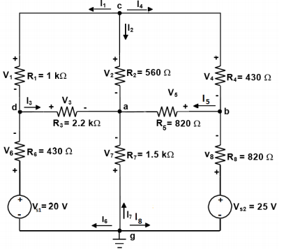
Homework Answers
Request Answer!
We need at least 10 more requests to produce the answer.
0 / 10 have requested this problem solution
The more requests, the faster the answer.
Add Answer to:
Solve this circuit using node-voltage method. Determine the
currents through all the elements and voltages across...
2. (2000) Electromagnetics (DC Circuit) Problem a. Calculate the voltages across all resistors and the currents through all the resistors and voltage sources in the following circuit using Kirchhoff&...
 2. (2000) Electromagnetics (DC Circuit) Problem a. Calculate the voltages across all resistors and the currents through all the resistors and voltage sources in the following circuit using Kirchhoff's junction rule (nodal analysis). Show the directions initially assumed for the junction (node) currents. Use the minimum number of junctions (nodes) necessary to accomplish this b. Calculate the power dissipation in each resistor and the sum (or total) of these individual power dissipation values c. Calculate the power associated with each...
Node Voltage Method Example 4: find v2 1,-24,1-3A, Ri-20,R,-40,R,-20,R,-30 . Label currents and voltages (polarities "arbitrarily"...
 Node Voltage Method Example 4: find v2 1,-24,1-3A, Ri-20,R,-40,R,-20,R,-30 . Label currents and voltages (polarities "arbitrarily" chosen) + R3- 1. 2. Choose Node d (v) as the reference node 3. Define remaining n -1 (3) voltages 2 (Vd 0) Va is independent V, is independent >Ve is independent 4. Apply KCL at nodes a, b, and c 1/27/2019 Node and Mesh Methods
Solve each practice problem. TYPE solutions in engineering notation TYPE solutions in engineering notation. Calcula...
 Solve each practice problem. TYPE solutions in
engineering notation
TYPE solutions in engineering
notation.
Calculate the component voltages and branch currents for the circuit shown in Figure 6.40, along with the values of I, and Rr. 3. R3 2 kn R4 4.7 k R1 10 k Vs 26 V R5 3.3 k R2 3 kn FIGURE 6.40 Calculate the component currents and loop voltages for the circuit shown in Figure 6.42, along with the values of I and Rr 5....
Solve each practice problem. TYPE solutions in
engineering notation
TYPE solutions in engineering
notation.
Calculate the component voltages and branch currents for the circuit shown in Figure 6.40, along with the values of I, and Rr. 3. R3 2 kn R4 4.7 k R1 10 k Vs 26 V R5 3.3 k R2 3 kn FIGURE 6.40 Calculate the component currents and loop voltages for the circuit shown in Figure 6.42, along with the values of I and Rr 5....
Learning Goal: To use the node-voltage method to solve circuits that contain resistors and independent sources....
 Learning Goal: To use the node-voltage method to solve circuits that contain resistors and independent sources. The node-voltage method is a general technique for solving circuits. Fundamentally, it involves writing KCL equations at essential nodes. You should review KCL and the definition of an essential node before beginning. In this tutorial, you will use the node-voltage method to find the current through the voltage source, io , and the voltage drop across the 5 kN resistor, vo, for the circuit...
Learning Goal: To use the node-voltage method to solve circuits with branches containing only a voltage...
 Learning Goal: To use the node-voltage method to solve circuits with branches containing only a voltage source. The node-voltage method is a general technique for solving circuits. Fundamentally, it involves writing KCL equations at essential nodes. When the circuit contains a dependent source, you must write a constraint equation for each dependent source, in addition to the KCL equations. When the circuit contains one or more voltage sources that are the only components in branches connecting two essential nodes, the...
R 0 Rz 3 + VA R3 + 3 VA Vg + Ig mm HU WW...
 R 0 Rz 3 + VA R3 + 3 VA Vg + Ig mm HU WW Ry you are given: Ri = R2 = Rs = RA 19, V, = 8V and 1, - 8A. a) Draw the graph and identify a tree that satisfies the guidelines (include resistor RA in the tree as well). b) Formulate and solve the node voltage equations in matrix form (stick to the given node numbering!). c) Compute all the powers, and verify that...
2) Use the circuit below to determine the following: a. Use mesh curre b. Use node-voltage...
 2) Use the circuit below to determine the following: a. Use mesh curre b. Use node-voltage to verify the currents i,- ie from part a. (10 pts) c. Show that th nt to find the branch currents for i,- ie for the circuit shown (10 pts) e total power developed in the circuit equals the total power consumed by the circuit. (5 pts) 5? 102 19 A 40 23ia 2 lb 240 V
Voltage and Current Division For the circuit shown, calculate V. V and Vs when V. =...
 Voltage and Current Division For the circuit shown, calculate V. V and Vs when V. = 7 V, R; = 18 2. R2 = 66 2. R3 = 57 2. R4 = 37 and Rs = 332 Express your answer to two significant figures, with appropriate units View Available Hint(s) @? R-180 R2 = 660 + V + 12 0.597 V = 7 V R3 - 570 V 1.89 V R$ = 33 R = 37 Vs + - V4...
Use measured resistance values and node analysis to calculate the node voltages. Use measured resistance values...
 Use measured resistance values and node analysis to calculate
the node voltages.
Use measured resistance values and mesh analysis to calculate
the mesh currents.
Show that the calculated values agree with the measured values
and explain any discrepancies between measured and calculated
values.
Introduction: In this pre-lab we will look at node voltages, mesh currents and bridge circuits. Bridge Circuits are used to make precision measurements, and in this lab -- -0 V2 will look at a DC Bridge Circuit...
Use measured resistance values and node analysis to calculate
the node voltages.
Use measured resistance values and mesh analysis to calculate
the mesh currents.
Show that the calculated values agree with the measured values
and explain any discrepancies between measured and calculated
values.
Introduction: In this pre-lab we will look at node voltages, mesh currents and bridge circuits. Bridge Circuits are used to make precision measurements, and in this lab -- -0 V2 will look at a DC Bridge Circuit...
Please do parts b-d. 2. Consider the circuit shown below. 0.2i 7 2 4Ω 1Ω 4Ω 0.1 va (a) By hand, use any method (node voltage, mesh currents, etc.) tosolve for the currentix b) Using Spice, solve for...
 Please do parts b-d.
2. Consider the circuit shown below. 0.2i 7 2 4Ω 1Ω 4Ω 0.1 va (a) By hand, use any method (node voltage, mesh currents, etc.) tosolve for the currentix b) Using Spice, solve for ix and compare with your hand calculation. (c) Plot Va vs. Vs, where Vs replaces the 9 V voltage source (and has the same polarity) and varies from -20 to 20 volts. At what value of Vs does the direction of the...
Please do parts b-d.
2. Consider the circuit shown below. 0.2i 7 2 4Ω 1Ω 4Ω 0.1 va (a) By hand, use any method (node voltage, mesh currents, etc.) tosolve for the currentix b) Using Spice, solve for ix and compare with your hand calculation. (c) Plot Va vs. Vs, where Vs replaces the 9 V voltage source (and has the same polarity) and varies from -20 to 20 volts. At what value of Vs does the direction of the...
 2. (2000) Electromagnetics (DC Circuit) Problem a. Calculate the voltages across all resistors and the currents through all the resistors and voltage sources in the following circuit using Kirchhoff's junction rule (nodal analysis). Show the directions initially assumed for the junction (node) currents. Use the minimum number of junctions (nodes) necessary to accomplish this b. Calculate the power dissipation in each resistor and the sum (or total) of these individual power dissipation values c. Calculate the power associated with each...
 Node Voltage Method Example 4: find v2 1,-24,1-3A, Ri-20,R,-40,R,-20,R,-30 . Label currents and voltages (polarities "arbitrarily" chosen) + R3- 1. 2. Choose Node d (v) as the reference node 3. Define remaining n -1 (3) voltages 2 (Vd 0) Va is independent V, is independent >Ve is independent 4. Apply KCL at nodes a, b, and c 1/27/2019 Node and Mesh Methods
 Solve each practice problem. TYPE solutions in
engineering notation
TYPE solutions in engineering
notation.
Calculate the component voltages and branch currents for the circuit shown in Figure 6.40, along with the values of I, and Rr. 3. R3 2 kn R4 4.7 k R1 10 k Vs 26 V R5 3.3 k R2 3 kn FIGURE 6.40 Calculate the component currents and loop voltages for the circuit shown in Figure 6.42, along with the values of I and Rr 5....
Solve each practice problem. TYPE solutions in
engineering notation
TYPE solutions in engineering
notation.
Calculate the component voltages and branch currents for the circuit shown in Figure 6.40, along with the values of I, and Rr. 3. R3 2 kn R4 4.7 k R1 10 k Vs 26 V R5 3.3 k R2 3 kn FIGURE 6.40 Calculate the component currents and loop voltages for the circuit shown in Figure 6.42, along with the values of I and Rr 5....
 Learning Goal: To use the node-voltage method to solve circuits that contain resistors and independent sources. The node-voltage method is a general technique for solving circuits. Fundamentally, it involves writing KCL equations at essential nodes. You should review KCL and the definition of an essential node before beginning. In this tutorial, you will use the node-voltage method to find the current through the voltage source, io , and the voltage drop across the 5 kN resistor, vo, for the circuit...
 Learning Goal: To use the node-voltage method to solve circuits with branches containing only a voltage source. The node-voltage method is a general technique for solving circuits. Fundamentally, it involves writing KCL equations at essential nodes. When the circuit contains a dependent source, you must write a constraint equation for each dependent source, in addition to the KCL equations. When the circuit contains one or more voltage sources that are the only components in branches connecting two essential nodes, the...
 R 0 Rz 3 + VA R3 + 3 VA Vg + Ig mm HU WW Ry you are given: Ri = R2 = Rs = RA 19, V, = 8V and 1, - 8A. a) Draw the graph and identify a tree that satisfies the guidelines (include resistor RA in the tree as well). b) Formulate and solve the node voltage equations in matrix form (stick to the given node numbering!). c) Compute all the powers, and verify that...
 2) Use the circuit below to determine the following: a. Use mesh curre b. Use node-voltage to verify the currents i,- ie from part a. (10 pts) c. Show that th nt to find the branch currents for i,- ie for the circuit shown (10 pts) e total power developed in the circuit equals the total power consumed by the circuit. (5 pts) 5? 102 19 A 40 23ia 2 lb 240 V
 Voltage and Current Division For the circuit shown, calculate V. V and Vs when V. = 7 V, R; = 18 2. R2 = 66 2. R3 = 57 2. R4 = 37 and Rs = 332 Express your answer to two significant figures, with appropriate units View Available Hint(s) @? R-180 R2 = 660 + V + 12 0.597 V = 7 V R3 - 570 V 1.89 V R$ = 33 R = 37 Vs + - V4...
 Use measured resistance values and node analysis to calculate
the node voltages.
Use measured resistance values and mesh analysis to calculate
the mesh currents.
Show that the calculated values agree with the measured values
and explain any discrepancies between measured and calculated
values.
Introduction: In this pre-lab we will look at node voltages, mesh currents and bridge circuits. Bridge Circuits are used to make precision measurements, and in this lab -- -0 V2 will look at a DC Bridge Circuit...
Use measured resistance values and node analysis to calculate
the node voltages.
Use measured resistance values and mesh analysis to calculate
the mesh currents.
Show that the calculated values agree with the measured values
and explain any discrepancies between measured and calculated
values.
Introduction: In this pre-lab we will look at node voltages, mesh currents and bridge circuits. Bridge Circuits are used to make precision measurements, and in this lab -- -0 V2 will look at a DC Bridge Circuit...
 Please do parts b-d.
2. Consider the circuit shown below. 0.2i 7 2 4Ω 1Ω 4Ω 0.1 va (a) By hand, use any method (node voltage, mesh currents, etc.) tosolve for the currentix b) Using Spice, solve for ix and compare with your hand calculation. (c) Plot Va vs. Vs, where Vs replaces the 9 V voltage source (and has the same polarity) and varies from -20 to 20 volts. At what value of Vs does the direction of the...
Please do parts b-d.
2. Consider the circuit shown below. 0.2i 7 2 4Ω 1Ω 4Ω 0.1 va (a) By hand, use any method (node voltage, mesh currents, etc.) tosolve for the currentix b) Using Spice, solve for ix and compare with your hand calculation. (c) Plot Va vs. Vs, where Vs replaces the 9 V voltage source (and has the same polarity) and varies from -20 to 20 volts. At what value of Vs does the direction of the...
Most questions answered within 3 hours.
-
Write a psudocode:
1. Define a function called authorize that takes in 2 strings,
uName, and...
asked 5 minutes ago -
What Hall voltage (in mV) is produced by a 0.180 T field applied
across a 2.60...
asked 3 minutes ago -
What mass of ethylene glycol (C2H6O2) must be added to 211.0 g
of water to obtain...
asked 6 minutes ago -
Mary's employer has a defined benefits retirement plan, which
pay 3.2% of her last year's salary...
asked 9 minutes ago -
What are the characteristics and behavior of an ethical
manager?
Explain, in your words, what ethics...
asked 26 minutes ago -
1. Which of the following is NOT an argument that McMahan uses
to show that jus...
asked 47 minutes ago -
A crate slides up a frictionless slope. At the end of 3 seconds
its velocity is...
asked 1 hour ago -
Use the following information to answer the next seven
questions.
Suppose there are three potential states...
asked 1 hour ago -
If we only have interstitial and substitutional diffusion, then
what do we consider the process of...
asked 1 hour ago -
You look at yourself in a shiny 9.6-cm-diameter Christmas tree
ball.
If your face is 21.0...
asked 1 hour ago -
If we were to measure the relaxation time of a muscle after
undergoing tetanus compared to...
asked 1 hour ago -
4CO(g) + 8H2(g) -----> 3CH4(g) +
CO2(g) + 2H2O(l)
Use the following data as needed to...
asked 1 hour ago