
Homework Answers
 
 be
entertained for sure but please upvote my work
be
entertained for sure but please upvote my work
Add Answer to:
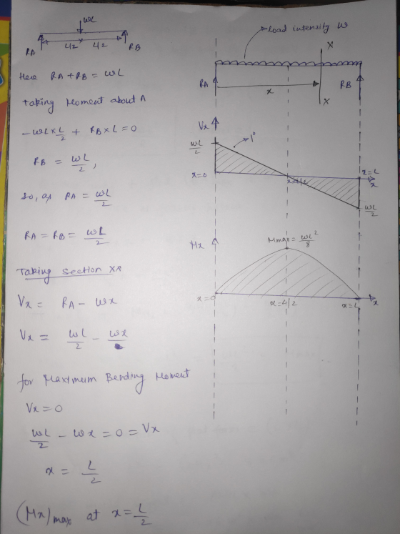
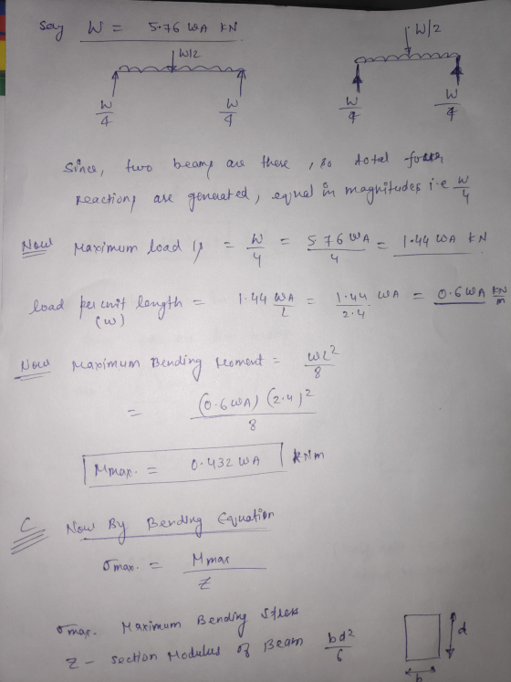
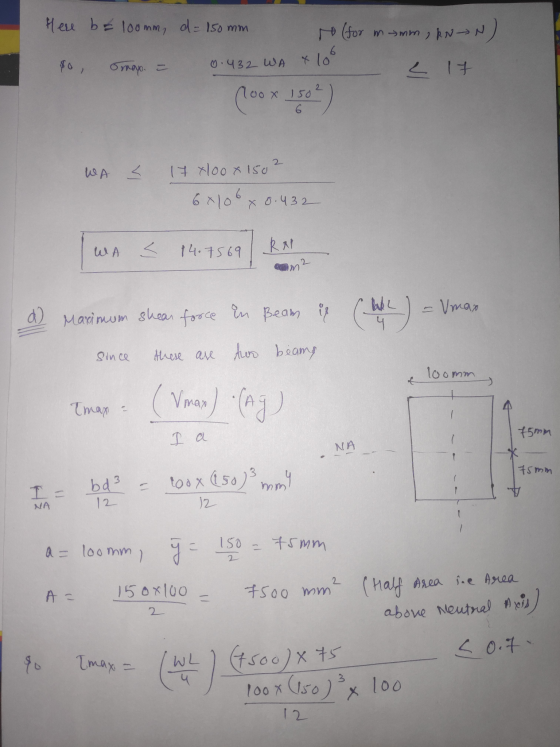
Question 2 (25 marks) A square wood platform of side-length L = 2.4 m rests on...
A square wood platform of side-length ? = 2.4 m rests on masonry walls. The deck...
 A square wood platform of side-length ? = 2.4 m rests on masonry
walls. The deck of the platform is constructed of 4 cm thick planks
supported on two beams which are 2.4 m long. The beams have a width
of 100 mm and height of 150 mm and are supported at their ends by
the walls. The structure is designed to support a uniformly
distributed load, ?? (kN/m2), acting over the entire top surface of
the platform. The tensile...
A square wood platform of side-length ? = 2.4 m rests on masonry
walls. The deck of the platform is constructed of 4 cm thick planks
supported on two beams which are 2.4 m long. The beams have a width
of 100 mm and height of 150 mm and are supported at their ends by
the walls. The structure is designed to support a uniformly
distributed load, ?? (kN/m2), acting over the entire top surface of
the platform. The tensile...
1.2 (20 Marks) A beam of rectangular cross section (width b and height h) supports a...
 1.2 (20 Marks) A beam of rectangular cross section (width b and height h) supports a uniformly distributed load along its entire length L. The allowable stresses in bending and shear are all and Tallow, respectively. a) If the beam is simply supported, what is the span length Lo below which the shear stress governs the allowable load and above which the bending stress governs? b) If the beam is supported as a cantilever, what is the length Lo below...
A simply supported wood beam of rectangular cross section and span length 2 m carries a...
 A simply supported wood beam of rectangular cross section and span length 2 m carries a uniformly distributed load of intensity 9 = 1 kN/m as shown. Calculate the maximum bending stress and the maximum shear stress in the beam.
QUESTION 2 Beam ABCD is 8 m in length and is pin-supported at A and roller-supported...
 QUESTION 2 Beam ABCD is 8 m in length and is pin-supported at A and roller-supported at C as shown in Figure Q2. A counter-clockwise concentrated moment acts about the support A. A uniformly-distributed load acts on span BC and a vertical concentrated load acts at the free end D a) Determine the reactions at supports A and C. 4 marks) b) Obtain the shear force and the bending moment functions (in terms of x) for each segment along the...
A5.2 m long simply supported wood beam carries a uniformly distributed load of 12.9 kN/m, as...
 A5.2 m long simply supported wood beam carries a uniformly distributed load of 12.9 kN/m, as shown in Figure A. The cross-sectional dimensions of the beam as shown in Figure Bare b = 195 mm, d = 485 mm. yy = 81 mm, and yx = 167 mm. Section 3-a is located at x = 1.4 m from B. (a) At section a-a, determine the magnitude of the shear stress in the beam at point H. (b) At section a-3,...
2 A simply supported beam of length L = 10 m carries both a uniformly distributed...
 2 A simply supported beam of length L = 10 m carries both a uniformly distributed load w, of 10 kN/m and a non-uniformly distributed load with a maximum value of w2 =10 kN/m at its roller support, as shown in Figure Q2 (a). The beam is made from a I-section and the thickness for all the three rectangular members is of 10 mm. All other dimensions are illustrated in Figure 02 (b). Self-weight of the beam is neglected. 300...
Question 2: A simply supported beam under loading as shown in Figure 1: 1. Draw the influence lines of the bending moment and shear force at point C (L/4) Using the influence lines to determine t...
 Question 2: A simply supported beam under loading as shown in Figure 1: 1. Draw the influence lines of the bending moment and shear force at point C (L/4) Using the influence lines to determine the bending moment and shear force at section C due to the loading as shown in the figure. 2. 3. There is a distributed live load (w#2.5kN/m) which can vary the location along the beam. Determine the location of the live loads which create the...
The simply-supported beam having I-beam cross-section as shown in figure is to carry a uniformly distributed...
 The simply-supported beam having I-beam cross-section as shown in figure is to carry a uniformly distributed load over its entire 1.2m length. Specify the maximum allowable load if the beam is made from malleable iron, ASTM A220, class 80002. The allowable tensile stress is 164 MPa and allowable compressive stress is 412 MPa. The centroid of the section is located at 35 mm from the bottom and moment of inertia are Ix = 2.66 x 10 mm". (a) Draw loading...
reinforced concrete design , ACI code Shear Strength of Flexural Members Design for shear forces The...
 reinforced concrete design , ACI code
Shear Strength of Flexural Members Design for shear forces The simply supported beam shown is subjected to ultimate (factored) distributed and concentrated loads 1. Determine the shear capacity of concrete at the critical section according to ACI318-14 detailed method in Table 22.5.5.1. Design the shear reinforcement and determine the locations on the beam shear force diagram where this shear reinforcement should be placed. 2. 3. Determine the locations within the beam where minimum shear...
reinforced concrete design , ACI code
Shear Strength of Flexural Members Design for shear forces The simply supported beam shown is subjected to ultimate (factored) distributed and concentrated loads 1. Determine the shear capacity of concrete at the critical section according to ACI318-14 detailed method in Table 22.5.5.1. Design the shear reinforcement and determine the locations on the beam shear force diagram where this shear reinforcement should be placed. 2. 3. Determine the locations within the beam where minimum shear...
A wood beam (1) is reinforced on its lower surface by a steel plate (2) as...
 A wood beam (1) is reinforced on its lower surface by a steel
plate (2) as shown in the figure. Dimensions of the cross section
are b 1 = 220 mm , d = 385 mm , b 2 = 190 mm , and t = 25 mm . The
elastic moduli of the wood and steel are E 1 = 12.5 GPa and E 2 =
200 GPa , respectively. The allowable bending stresses of the wood
and steel...
A wood beam (1) is reinforced on its lower surface by a steel
plate (2) as shown in the figure. Dimensions of the cross section
are b 1 = 220 mm , d = 385 mm , b 2 = 190 mm , and t = 25 mm . The
elastic moduli of the wood and steel are E 1 = 12.5 GPa and E 2 =
200 GPa , respectively. The allowable bending stresses of the wood
and steel...
 A square wood platform of side-length ? = 2.4 m rests on masonry
walls. The deck of the platform is constructed of 4 cm thick planks
supported on two beams which are 2.4 m long. The beams have a width
of 100 mm and height of 150 mm and are supported at their ends by
the walls. The structure is designed to support a uniformly
distributed load, ?? (kN/m2), acting over the entire top surface of
the platform. The tensile...
A square wood platform of side-length ? = 2.4 m rests on masonry
walls. The deck of the platform is constructed of 4 cm thick planks
supported on two beams which are 2.4 m long. The beams have a width
of 100 mm and height of 150 mm and are supported at their ends by
the walls. The structure is designed to support a uniformly
distributed load, ?? (kN/m2), acting over the entire top surface of
the platform. The tensile...
 1.2 (20 Marks) A beam of rectangular cross section (width b and height h) supports a uniformly distributed load along its entire length L. The allowable stresses in bending and shear are all and Tallow, respectively. a) If the beam is simply supported, what is the span length Lo below which the shear stress governs the allowable load and above which the bending stress governs? b) If the beam is supported as a cantilever, what is the length Lo below...
 QUESTION 2 Beam ABCD is 8 m in length and is pin-supported at A and roller-supported at C as shown in Figure Q2. A counter-clockwise concentrated moment acts about the support A. A uniformly-distributed load acts on span BC and a vertical concentrated load acts at the free end D a) Determine the reactions at supports A and C. 4 marks) b) Obtain the shear force and the bending moment functions (in terms of x) for each segment along the...
 A5.2 m long simply supported wood beam carries a uniformly distributed load of 12.9 kN/m, as shown in Figure A. The cross-sectional dimensions of the beam as shown in Figure Bare b = 195 mm, d = 485 mm. yy = 81 mm, and yx = 167 mm. Section 3-a is located at x = 1.4 m from B. (a) At section a-a, determine the magnitude of the shear stress in the beam at point H. (b) At section a-3,...
 2 A simply supported beam of length L = 10 m carries both a uniformly distributed load w, of 10 kN/m and a non-uniformly distributed load with a maximum value of w2 =10 kN/m at its roller support, as shown in Figure Q2 (a). The beam is made from a I-section and the thickness for all the three rectangular members is of 10 mm. All other dimensions are illustrated in Figure 02 (b). Self-weight of the beam is neglected. 300...
 Question 2: A simply supported beam under loading as shown in Figure 1: 1. Draw the influence lines of the bending moment and shear force at point C (L/4) Using the influence lines to determine the bending moment and shear force at section C due to the loading as shown in the figure. 2. 3. There is a distributed live load (w#2.5kN/m) which can vary the location along the beam. Determine the location of the live loads which create the...
 The simply-supported beam having I-beam cross-section as shown in figure is to carry a uniformly distributed load over its entire 1.2m length. Specify the maximum allowable load if the beam is made from malleable iron, ASTM A220, class 80002. The allowable tensile stress is 164 MPa and allowable compressive stress is 412 MPa. The centroid of the section is located at 35 mm from the bottom and moment of inertia are Ix = 2.66 x 10 mm". (a) Draw loading...
 reinforced concrete design , ACI code
Shear Strength of Flexural Members Design for shear forces The simply supported beam shown is subjected to ultimate (factored) distributed and concentrated loads 1. Determine the shear capacity of concrete at the critical section according to ACI318-14 detailed method in Table 22.5.5.1. Design the shear reinforcement and determine the locations on the beam shear force diagram where this shear reinforcement should be placed. 2. 3. Determine the locations within the beam where minimum shear...
reinforced concrete design , ACI code
Shear Strength of Flexural Members Design for shear forces The simply supported beam shown is subjected to ultimate (factored) distributed and concentrated loads 1. Determine the shear capacity of concrete at the critical section according to ACI318-14 detailed method in Table 22.5.5.1. Design the shear reinforcement and determine the locations on the beam shear force diagram where this shear reinforcement should be placed. 2. 3. Determine the locations within the beam where minimum shear...
 A wood beam (1) is reinforced on its lower surface by a steel
plate (2) as shown in the figure. Dimensions of the cross section
are b 1 = 220 mm , d = 385 mm , b 2 = 190 mm , and t = 25 mm . The
elastic moduli of the wood and steel are E 1 = 12.5 GPa and E 2 =
200 GPa , respectively. The allowable bending stresses of the wood
and steel...
A wood beam (1) is reinforced on its lower surface by a steel
plate (2) as shown in the figure. Dimensions of the cross section
are b 1 = 220 mm , d = 385 mm , b 2 = 190 mm , and t = 25 mm . The
elastic moduli of the wood and steel are E 1 = 12.5 GPa and E 2 =
200 GPa , respectively. The allowable bending stresses of the wood
and steel...
Most questions answered within 3 hours.
-
1. Why is the Electron Affinity of chlorine more favorable (that
is, more negative) than fluorine?...
asked 15 minutes ago -
What is the isotactic cycle kf alkene. Draw its
catalytic cylce
asked 16 minutes ago -
What is the rate constant for a reaction based on the following
experimental information?
Experiment
Rate...
asked 18 minutes ago -
1. In biology, the term "ionic bond" is used differently than in
chemistry. A biological "ionic...
asked 29 minutes ago -
write the sequence of the GFP and primer DNAs, showing each of
the primers annealed to...
asked 34 minutes ago -
19.) A zero coupon bond matures in 7 years and sells for $695.
If the tax...
asked 35 minutes ago -
In Java
#2 JAVA Write a program named salaryCalculator that accepts
input from the user that...
asked 43 minutes ago -
Why is it desirable to remove insignificant variables
from regression?
asked 39 minutes ago -
Find the electric flux through a spherical surface of
radius 5.0 mm centered on a charge of...
asked 56 minutes ago -
TB 06-108 Martock Company uses the periodic inventory ...
Martock Company uses the periodic inventory system....
asked 48 minutes ago -
If 50 J of heat are absorbed from gold necklace with mass of
0.018 kg, what...
asked 46 minutes ago -
Determine the ratio of Earth's gravitational force exerted on an
80-kg person when at Earth's surface...
asked 48 minutes ago