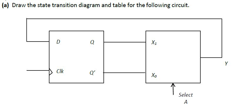
state transition diagram and table
Homework Answers
Request Answer!
We need at least 10 more requests to produce the answer.
0 / 10 have requested this problem solution
The more requests, the faster the answer.
18. For the following circuit find the state transition table and the stato transition diagram. K...
 18. For the following circuit find the state transition table and the stato transition diagram. K Q CLOCK
18. For the following circuit find the state transition table and the stato transition diagram. K Q CLOCK
18. For the following circuit find the state transition table and the stato transition diagram. K Q CLOCK
2. A sequential circuit is given below. The states in the transition diagram are labeled AB, e.g., the state corresponding to the sequential circuit are X and Y, and its output is Z. Draw a complete...
 2. A sequential circuit is given below. The states in the transition diagram are labeled AB, e.g., the state corresponding to the sequential circuit are X and Y, and its output is Z. Draw a complete state transition diagram for the circuit. J. A
2. A sequential circuit is given below. The states in the transition diagram are labeled AB, e.g., the state corresponding to the sequential circuit are X and Y, and its output is Z. Draw a complete...
2. A sequential circuit is given below. The states in the transition diagram are labeled AB, e.g., the state corresponding to the sequential circuit are X and Y, and its output is Z. Draw a complete state transition diagram for the circuit. J. A
2. A sequential circuit is given below. The states in the transition diagram are labeled AB, e.g., the state corresponding to the sequential circuit are X and Y, and its output is Z. Draw a complete...
26. A counter is shown below. К, Q, К Q, CLOCK a. Find the state transition table and diagram. b....
 26. A counter is shown below. К, Q, К Q, CLOCK a. Find the state transition table and diagram. b. Show the count sequence. c. What is the mod of this counter? d. Modify this circuit so that it becomes self-starting, ie. it can enter the count sequence from any initial state. 13
26. A counter is shown below. К, Q, К Q, CLOCK a. Find the state transition table and diagram. b. Show the count sequence. c. What is...
26. A counter is shown below. К, Q, К Q, CLOCK a. Find the state transition table and diagram. b. Show the count sequence. c. What is the mod of this counter? d. Modify this circuit so that it becomes self-starting, ie. it can enter the count sequence from any initial state. 13
26. A counter is shown below. К, Q, К Q, CLOCK a. Find the state transition table and diagram. b. Show the count sequence. c. What is...
Analyze the sequential counter circuit shown in figure 5.1. Derive the state transition table and diagram....
 Analyze the sequential counter
circuit shown in figure 5.1. Derive the state transition table and
diagram.
7400 U1 7400 01. 74x73 U2 4 74x13 76x73 Ly, QH122 7400 Reset (11) Clock - Figure 5.1
Analyze the sequential counter
circuit shown in figure 5.1. Derive the state transition table and
diagram.
7400 U1 7400 01. 74x73 U2 4 74x13 76x73 Ly, QH122 7400 Reset (11) Clock - Figure 5.1
Table Q4.1 shows the state transition table for a finite state machine (FSM) with one input...
 Table Q4.1 shows the state transition table for a finite state
machine (FSM) with one input x, one output z and eight states.
(a) Copy the table of Table Q4.2 into your examination book and
determine the states and outputs for the input listed, assuming a
start current state of ‘1’. Determine what function the FSM is
performing.
(b) Using the implication chart method, determine the minimal
number of states. Show clearly your analysis.
(c) Draw the reduced state transition...
Table Q4.1 shows the state transition table for a finite state
machine (FSM) with one input x, one output z and eight states.
(a) Copy the table of Table Q4.2 into your examination book and
determine the states and outputs for the input listed, assuming a
start current state of ‘1’. Determine what function the FSM is
performing.
(b) Using the implication chart method, determine the minimal
number of states. Show clearly your analysis.
(c) Draw the reduced state transition...
Thc state transition table bclow is for a sequential circuit with onc input X and onc output Y. The circuit has two state variables A and B, and synchronous input Reset that resets the circuit to sta...
 Thc state transition table bclow is for a sequential circuit with onc input X and onc output Y. The circuit has two state variables A and B, and synchronous input Reset that resets the circuit to state AB-01 when Reset 1: Present State Next State Output X-0 A B A B 0 Reset State 0 0 (9 points) Implement the sequential circuit using minimum number of logic gates and rising- edge triggered D-FFs and draw the logic diagram of the...
Software Engineering Question Use an example to explain state transition diagram and draw the diagram.
Software Engineering Question Use an example to explain state transition diagram and draw the diagram.
Draw a state diagram and state table and show what if anything is wrong with the following synchronous state machine
 1. (a) Draw a state diagram and state table and show what if anything is wrong with the following synchronous state machine that has asynchronous input \(\mathrm{X}\) and state variables \(\mathrm{A} \& \mathrm{~B}\) ?(b) If possible, draw a new circuit (without adding or removing any flip-flops) that has the same functionality but fixes any problem with the circuit. Also, show the new state diagram and state table.
Question: ###State Transition Diagram### This task requires you to develop a state chart diagram for an Ora... ###State Transition Diagram### This task requires you to develop a state chart diagram fo...
Question: ###State Transition Diagram### This task requires you to develop a state chart diagram for an Ora... ###State Transition Diagram### This task requires you to develop a state chart diagram for an Oral B Braun 5000 electric toothbrush. Starting from the user manual you should first analyze the functionality of the toothbrush and its interaction with the SmartGuide and then, using suitable software, produce a state transition diagram which covers both. Your state chart diagram will be demonstrated subjected to...
Consider the following FSM state transition diagram: 7. Let's see if there is an equivalent state machine with fewe...
 Consider the following FSM state transition diagram: 7. Let's see if there is an equivalent state machine with fewer states by checking to see if any states in the diagram above are equivalent. Two states are equivalent if (1) they have identical outputs and (2) for each possible combination of inputs they transition to equivalent states. A. Start by filling in a "compatibility table" like the one shown below. Place an "X" in square (SISI) if SI produces a different...
 18. For the following circuit find the state transition table and the stato transition diagram. K Q CLOCK
18. For the following circuit find the state transition table and the stato transition diagram. K Q CLOCK
18. For the following circuit find the state transition table and the stato transition diagram. K Q CLOCK
 2. A sequential circuit is given below. The states in the transition diagram are labeled AB, e.g., the state corresponding to the sequential circuit are X and Y, and its output is Z. Draw a complete state transition diagram for the circuit. J. A
2. A sequential circuit is given below. The states in the transition diagram are labeled AB, e.g., the state corresponding to the sequential circuit are X and Y, and its output is Z. Draw a complete...
2. A sequential circuit is given below. The states in the transition diagram are labeled AB, e.g., the state corresponding to the sequential circuit are X and Y, and its output is Z. Draw a complete state transition diagram for the circuit. J. A
2. A sequential circuit is given below. The states in the transition diagram are labeled AB, e.g., the state corresponding to the sequential circuit are X and Y, and its output is Z. Draw a complete...
 26. A counter is shown below. К, Q, К Q, CLOCK a. Find the state transition table and diagram. b. Show the count sequence. c. What is the mod of this counter? d. Modify this circuit so that it becomes self-starting, ie. it can enter the count sequence from any initial state. 13
26. A counter is shown below. К, Q, К Q, CLOCK a. Find the state transition table and diagram. b. Show the count sequence. c. What is...
26. A counter is shown below. К, Q, К Q, CLOCK a. Find the state transition table and diagram. b. Show the count sequence. c. What is the mod of this counter? d. Modify this circuit so that it becomes self-starting, ie. it can enter the count sequence from any initial state. 13
26. A counter is shown below. К, Q, К Q, CLOCK a. Find the state transition table and diagram. b. Show the count sequence. c. What is...
 Analyze the sequential counter
circuit shown in figure 5.1. Derive the state transition table and
diagram.
7400 U1 7400 01. 74x73 U2 4 74x13 76x73 Ly, QH122 7400 Reset (11) Clock - Figure 5.1
Analyze the sequential counter
circuit shown in figure 5.1. Derive the state transition table and
diagram.
7400 U1 7400 01. 74x73 U2 4 74x13 76x73 Ly, QH122 7400 Reset (11) Clock - Figure 5.1
 Table Q4.1 shows the state transition table for a finite state
machine (FSM) with one input x, one output z and eight states.
(a) Copy the table of Table Q4.2 into your examination book and
determine the states and outputs for the input listed, assuming a
start current state of ‘1’. Determine what function the FSM is
performing.
(b) Using the implication chart method, determine the minimal
number of states. Show clearly your analysis.
(c) Draw the reduced state transition...
Table Q4.1 shows the state transition table for a finite state
machine (FSM) with one input x, one output z and eight states.
(a) Copy the table of Table Q4.2 into your examination book and
determine the states and outputs for the input listed, assuming a
start current state of ‘1’. Determine what function the FSM is
performing.
(b) Using the implication chart method, determine the minimal
number of states. Show clearly your analysis.
(c) Draw the reduced state transition...
 Thc state transition table bclow is for a sequential circuit with onc input X and onc output Y. The circuit has two state variables A and B, and synchronous input Reset that resets the circuit to state AB-01 when Reset 1: Present State Next State Output X-0 A B A B 0 Reset State 0 0 (9 points) Implement the sequential circuit using minimum number of logic gates and rising- edge triggered D-FFs and draw the logic diagram of the...
 1. (a) Draw a state diagram and state table and show what if anything is wrong with the following synchronous state machine that has asynchronous input \(\mathrm{X}\) and state variables \(\mathrm{A} \& \mathrm{~B}\) ?(b) If possible, draw a new circuit (without adding or removing any flip-flops) that has the same functionality but fixes any problem with the circuit. Also, show the new state diagram and state table.
 Consider the following FSM state transition diagram: 7. Let's see if there is an equivalent state machine with fewer states by checking to see if any states in the diagram above are equivalent. Two states are equivalent if (1) they have identical outputs and (2) for each possible combination of inputs they transition to equivalent states. A. Start by filling in a "compatibility table" like the one shown below. Place an "X" in square (SISI) if SI produces a different...
Most questions answered within 3 hours.
-
(63
#14)
which of the following statments best describes how chamging
the concentration of the substances...
asked 2 hours ago -
In the following reaction, which element is undergoing
oxidation: Na2SO3 + N2O --> N2 + Na2SO4...
asked 2 hours ago -
Which of the following pairs of ions have the same electron
configuration?
I: Br− and Se2−...
asked 5 hours ago -
The Foremost Composite Materials Company is planning a two-day
sales conference for October 19-20. The conference...
asked 5 hours ago -
3) Illustrate the observed pattern of relatedness of organisms
versus adaptations to specific conditions. This means...
asked 6 hours ago -
In winter a lake has a 0.35 m thick ice layer over 1.10 m of
water....
asked 7 hours ago -
Assuming the following has been encrypted with a Vigenere cipher
below, use the method(s) and assumptions...
asked 7 hours ago -
How would I use switch statements to write a program that will
take an input of...
asked 7 hours ago -
Imagine a reaction in which methane gas combusts at a constant
pressure of 1 atm and...
asked 7 hours ago -
Two parallel wires (each 12 m in length) are separated by a
distance of 0.065 m...
asked 7 hours ago -
Suppose there were three masses at the corner of uniform
equilateral triangle. The masses are m1...
asked 7 hours ago -
Situation: A building that is 618 m above the ground floor. How
many times would a...
asked 7 hours ago