
Homework Answers
Add Answer to:
26. A counter is shown below. К, Q, К Q, CLOCK a. Find the state transition table and diagram. b....
Analyze the sequential counter circuit shown in figure 5.1. Derive the state transition table and diagram....
 Analyze the sequential counter
circuit shown in figure 5.1. Derive the state transition table and
diagram.
7400 U1 7400 01. 74x73 U2 4 74x13 76x73 Ly, QH122 7400 Reset (11) Clock - Figure 5.1
Analyze the sequential counter
circuit shown in figure 5.1. Derive the state transition table and
diagram.
7400 U1 7400 01. 74x73 U2 4 74x13 76x73 Ly, QH122 7400 Reset (11) Clock - Figure 5.1
18. For the following circuit find the state transition table and the stato transition diagram. K...
 18. For the following circuit find the state transition table and the stato transition diagram. K Q CLOCK
18. For the following circuit find the state transition table and the stato transition diagram. K Q CLOCK
18. For the following circuit find the state transition table and the stato transition diagram. K Q CLOCK
[41 140 points En Reset Clock Analyze the clocked synchronous Modulo-8 Binary Counter [zyx] shown. The counter is initially reset at startup. Show the characteristic and excitation equations of t...
 [41 140 points En Reset Clock Analyze the clocked synchronous Modulo-8 Binary Counter [zyx] shown. The counter is initially reset at startup. Show the characteristic and excitation equations of the Enabled T Flip-Flops, as well the state-transition table. Draw the state diagram of the counter.
[41 140 points En Reset Clock Analyze the clocked synchronous Modulo-8 Binary Counter [zyx] shown. The counter is initially reset at startup. Show the characteristic and excitation equations of the Enabled T Flip-Flops, as well...
[41 140 points En Reset Clock Analyze the clocked synchronous Modulo-8 Binary Counter [zyx] shown. The counter is initially reset at startup. Show the characteristic and excitation equations of the Enabled T Flip-Flops, as well the state-transition table. Draw the state diagram of the counter.
[41 140 points En Reset Clock Analyze the clocked synchronous Modulo-8 Binary Counter [zyx] shown. The counter is initially reset at startup. Show the characteristic and excitation equations of the Enabled T Flip-Flops, as well...
3. A timing diagram below shows a D Flip-flop and the input clock. Show the transition...
 3. A timing diagram below shows a D Flip-flop and the input clock. Show the transition of the output Q at the positive transitions of the clock signal. Q 1 initially. Clk 4. Implement a 2-bit up-counter using D flip-flops. Show the circuit. 5. Implement a 2-bit down-counter using D flip-flops. Show the circuit. Transitions: 11->10->01->00->11->10->...
Consider a 4-bit binary counter that increments on every clock pulse. (a) Construct the state diagram for a counter that has an state variable word A3A2A1A0. (b) Construct the state table by assuming...
Consider a 4-bit binary counter that increments on every clock pulse. (a) Construct the state diagram for a counter that has an state variable word A3A2A1A0. (b) Construct the state table by assuming that the circuit consists of four D-type flip-flops with the inputs D3, D2, D1, D0 corresponding to the outputs A3, A2, A1, A0, respectively. (c) Determine the Boolean equations for the flip-flop inputs as functions of the state variables A3, A2, A1, A0, respectively. (d) Design the...
4) Analyze the circuit shown below by finding tits transition table 3 to 8 Decoder Y7 Y6 wa Y5 D Q Y4 Y2 Wo Y1 Q0 Clock. ansitun table 4) Analyze the circuit shown below by finding tits tran...
 4) Analyze the circuit shown below by finding tits transition table 3 to 8 Decoder Y7 Y6 wa Y5 D Q Y4 Y2 Wo Y1 Q0 Clock. ansitun table
4) Analyze the circuit shown below by finding tits transition table 3 to 8 Decoder Y7 Y6 wa Y5 D Q Y4 Y2 Wo Y1 Q0 Clock. ansitun table
4) Analyze the circuit shown below by finding tits transition table 3 to 8 Decoder Y7 Y6 wa Y5 D Q Y4 Y2 Wo Y1 Q0 Clock. ansitun table
solve 1 2 and 3 Problems 1 and 2 require a 7-segment display. You may want to re-use the display driver you developed in Lab 3. Use a push-button as the clock - the pushbuttons are debounced, whereas...
 solve 1 2 and 3
Problems 1 and 2 require a 7-segment display. You may want to re-use the display driver you developed in Lab 3. Use a push-button as the clock - the pushbuttons are debounced, whereas the slide switches are not. Remember to provide columnsfor lest data in your state lables (use the observed next state as the test data in problems I and 2, and the observed next state and preseni output as the lest data in...
solve 1 2 and 3
Problems 1 and 2 require a 7-segment display. You may want to re-use the display driver you developed in Lab 3. Use a push-button as the clock - the pushbuttons are debounced, whereas the slide switches are not. Remember to provide columnsfor lest data in your state lables (use the observed next state as the test data in problems I and 2, and the observed next state and preseni output as the lest data in...
please answer all thanks very much! Question 3 Shown below is a schematic diagram of a...
 please answer all thanks very much!
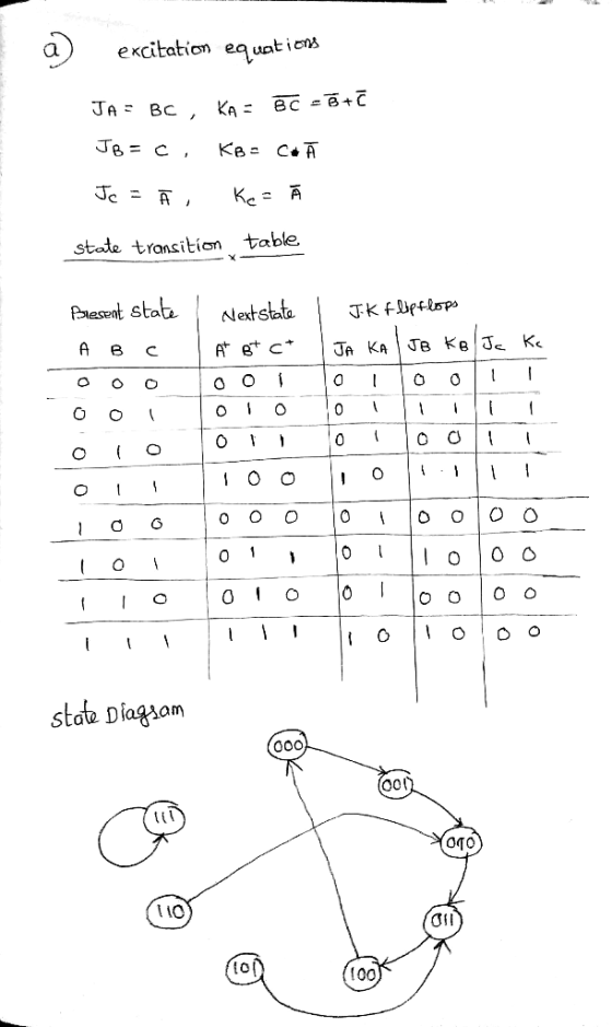
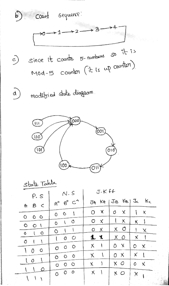
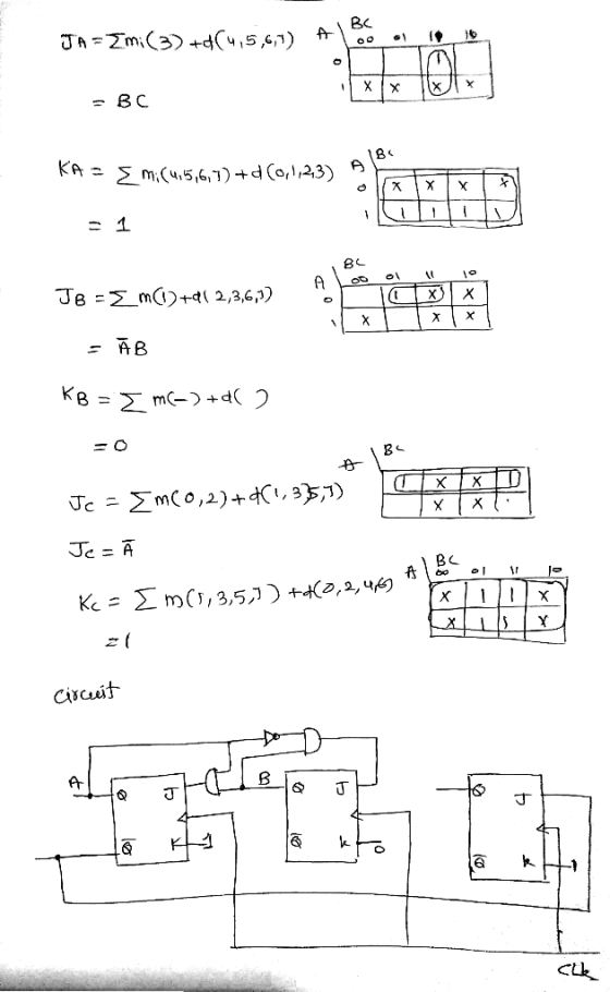
Question 3 Shown below is a schematic diagram of a counter made up of three JK flip-flops. (d) Shown below is a master-slave D flip-flop. This is made using two gated D latches. The truth table for a gated D latch is also shown below. HIGH J J CLK ас ас ac Truth table: gated D latch D EN D D, Q. D, 0. 0 0 go CLK ΕΝΟ ENO: 0 0 1 0...
please answer all thanks very much!
Question 3 Shown below is a schematic diagram of a counter made up of three JK flip-flops. (d) Shown below is a master-slave D flip-flop. This is made using two gated D latches. The truth table for a gated D latch is also shown below. HIGH J J CLK ас ас ac Truth table: gated D latch D EN D D, Q. D, 0. 0 0 go CLK ΕΝΟ ENO: 0 0 1 0...
A sequential circuit is to be designed with two input lines A - "Pres> 800" and...
 A sequential circuit is to be designed with two input lines A - "Pres> 800" and B Temp> 100" and a single outputX-"ALARM". If a clock pulse arrives when AB 00 the circuit is to assume a reset state which may be labeled SO. Suppose the next "3" clock pulses following a resetting pulse coincide with thoe following sequence of input conditions 01- 11 - 01 The output"ALARM" is to be"1" coinciding with the third of such a string of...
Design a synchronous sequential counter circuit that has the state diagram shown in figure 1. Use...
 Design a synchronous sequential counter circuit that has the state diagram shown in figure 1. Use both D-type and T-type Flip Flops in your design. Show all your work in details. Extra credit will be given for implementation using other types of Flip Flops 3 4 Figure 1 Deliverables: 1. State Transition Table 2. K-Maps 3. Logical Expressions (Minimal Form) 4. Schematic Diagrams of the two designs 5. Verification steps for both designs.
 Analyze the sequential counter
circuit shown in figure 5.1. Derive the state transition table and
diagram.
7400 U1 7400 01. 74x73 U2 4 74x13 76x73 Ly, QH122 7400 Reset (11) Clock - Figure 5.1
Analyze the sequential counter
circuit shown in figure 5.1. Derive the state transition table and
diagram.
7400 U1 7400 01. 74x73 U2 4 74x13 76x73 Ly, QH122 7400 Reset (11) Clock - Figure 5.1
 18. For the following circuit find the state transition table and the stato transition diagram. K Q CLOCK
18. For the following circuit find the state transition table and the stato transition diagram. K Q CLOCK
18. For the following circuit find the state transition table and the stato transition diagram. K Q CLOCK
 [41 140 points En Reset Clock Analyze the clocked synchronous Modulo-8 Binary Counter [zyx] shown. The counter is initially reset at startup. Show the characteristic and excitation equations of the Enabled T Flip-Flops, as well the state-transition table. Draw the state diagram of the counter.
[41 140 points En Reset Clock Analyze the clocked synchronous Modulo-8 Binary Counter [zyx] shown. The counter is initially reset at startup. Show the characteristic and excitation equations of the Enabled T Flip-Flops, as well...
[41 140 points En Reset Clock Analyze the clocked synchronous Modulo-8 Binary Counter [zyx] shown. The counter is initially reset at startup. Show the characteristic and excitation equations of the Enabled T Flip-Flops, as well the state-transition table. Draw the state diagram of the counter.
[41 140 points En Reset Clock Analyze the clocked synchronous Modulo-8 Binary Counter [zyx] shown. The counter is initially reset at startup. Show the characteristic and excitation equations of the Enabled T Flip-Flops, as well...
 3. A timing diagram below shows a D Flip-flop and the input clock. Show the transition of the output Q at the positive transitions of the clock signal. Q 1 initially. Clk 4. Implement a 2-bit up-counter using D flip-flops. Show the circuit. 5. Implement a 2-bit down-counter using D flip-flops. Show the circuit. Transitions: 11->10->01->00->11->10->...
 4) Analyze the circuit shown below by finding tits transition table 3 to 8 Decoder Y7 Y6 wa Y5 D Q Y4 Y2 Wo Y1 Q0 Clock. ansitun table
4) Analyze the circuit shown below by finding tits transition table 3 to 8 Decoder Y7 Y6 wa Y5 D Q Y4 Y2 Wo Y1 Q0 Clock. ansitun table
4) Analyze the circuit shown below by finding tits transition table 3 to 8 Decoder Y7 Y6 wa Y5 D Q Y4 Y2 Wo Y1 Q0 Clock. ansitun table
 solve 1 2 and 3
Problems 1 and 2 require a 7-segment display. You may want to re-use the display driver you developed in Lab 3. Use a push-button as the clock - the pushbuttons are debounced, whereas the slide switches are not. Remember to provide columnsfor lest data in your state lables (use the observed next state as the test data in problems I and 2, and the observed next state and preseni output as the lest data in...
solve 1 2 and 3
Problems 1 and 2 require a 7-segment display. You may want to re-use the display driver you developed in Lab 3. Use a push-button as the clock - the pushbuttons are debounced, whereas the slide switches are not. Remember to provide columnsfor lest data in your state lables (use the observed next state as the test data in problems I and 2, and the observed next state and preseni output as the lest data in...
 please answer all thanks very much!
Question 3 Shown below is a schematic diagram of a counter made up of three JK flip-flops. (d) Shown below is a master-slave D flip-flop. This is made using two gated D latches. The truth table for a gated D latch is also shown below. HIGH J J CLK ас ас ac Truth table: gated D latch D EN D D, Q. D, 0. 0 0 go CLK ΕΝΟ ENO: 0 0 1 0...
please answer all thanks very much!
Question 3 Shown below is a schematic diagram of a counter made up of three JK flip-flops. (d) Shown below is a master-slave D flip-flop. This is made using two gated D latches. The truth table for a gated D latch is also shown below. HIGH J J CLK ас ас ac Truth table: gated D latch D EN D D, Q. D, 0. 0 0 go CLK ΕΝΟ ENO: 0 0 1 0...
 A sequential circuit is to be designed with two input lines A - "Pres> 800" and B Temp> 100" and a single outputX-"ALARM". If a clock pulse arrives when AB 00 the circuit is to assume a reset state which may be labeled SO. Suppose the next "3" clock pulses following a resetting pulse coincide with thoe following sequence of input conditions 01- 11 - 01 The output"ALARM" is to be"1" coinciding with the third of such a string of...
 Design a synchronous sequential counter circuit that has the state diagram shown in figure 1. Use both D-type and T-type Flip Flops in your design. Show all your work in details. Extra credit will be given for implementation using other types of Flip Flops 3 4 Figure 1 Deliverables: 1. State Transition Table 2. K-Maps 3. Logical Expressions (Minimal Form) 4. Schematic Diagrams of the two designs 5. Verification steps for both designs.
Most questions answered within 3 hours.
-
Work of 1950 J is done by stirring a perfectly insulated beaker
containing 75 g of...
asked 10 minutes ago -
The neighborhood kids set up an outdoor lemonade stand in
Maryland in June. They find that...
asked 12 minutes ago -
9. A company has a beginning inventory of 4,000 units. The
company estimates it will sell...
asked 25 minutes ago -
A patient goes to the doctor's office with symptoms of a urinary
tract infection and provides...
asked 28 minutes ago -
When responding to the essay questions, be sure to cite any
material you obtained from a...
asked 28 minutes ago -
The energy of an electron in a 2.25-eV-deep potential well is
1.50 eV.At what distance into...
asked 30 minutes ago -
Q1:Which three evolutionary innovations are present in land
plants (but not all land plants) that allowed...
asked 32 minutes ago -
Lymphosarcoma is
extremely rare. Risk factors for the disease are largely unknown.
What kind of study...
asked 35 minutes ago -
The solubility of benzoic acid in water is:
0.29g/100mL at 20°C
6.8g/100mL at 100°C
a) What...
asked 36 minutes ago -
Which food law was passed in 1996 and changed how pesticide
residues on food were regulated...
asked 54 minutes ago -
companies either hire outside programmers to
write_____ software or use their own internal developers.
asked 53 minutes ago -
A magnetic dipole m(t) = m_0*cos(ωt) can be
described as current density j(r,t) = −cm(t) ×...
asked 53 minutes ago