
Homework Answers
Add Answer to:
18. For the following circuit find the state transition table and the stato transition diagram. K...
26. A counter is shown below. К, Q, К Q, CLOCK a. Find the state transition table and diagram. b....
 26. A counter is shown below. К, Q, К Q, CLOCK a. Find the state transition table and diagram. b. Show the count sequence. c. What is the mod of this counter? d. Modify this circuit so that it becomes self-starting, ie. it can enter the count sequence from any initial state. 13
26. A counter is shown below. К, Q, К Q, CLOCK a. Find the state transition table and diagram. b. Show the count sequence. c. What is...
26. A counter is shown below. К, Q, К Q, CLOCK a. Find the state transition table and diagram. b. Show the count sequence. c. What is the mod of this counter? d. Modify this circuit so that it becomes self-starting, ie. it can enter the count sequence from any initial state. 13
26. A counter is shown below. К, Q, К Q, CLOCK a. Find the state transition table and diagram. b. Show the count sequence. c. What is...
Analyze the sequential counter circuit shown in figure 5.1. Derive the state transition table and diagram....
 Analyze the sequential counter
circuit shown in figure 5.1. Derive the state transition table and
diagram.
7400 U1 7400 01. 74x73 U2 4 74x13 76x73 Ly, QH122 7400 Reset (11) Clock - Figure 5.1
Analyze the sequential counter
circuit shown in figure 5.1. Derive the state transition table and
diagram.
7400 U1 7400 01. 74x73 U2 4 74x13 76x73 Ly, QH122 7400 Reset (11) Clock - Figure 5.1
Write the state input and output equations, the state table, and the state diagram for the following circuit. Include at least one complete solution to each equation used to develop the truth tab...
 Write the state input and output equations, the state table, and the state diagram for the following circuit. Include at least one complete solution to each equation used to develop the truth table. K is connected to a logic high (1). Consider both CLK's to be connected to a proper external clock Also consider the PRE and CLR of each flip-flop to be connected to a logic high (1). 1. PRE PRE J Q K Q CLR dlo- CLR
Write...
Write the state input and output equations, the state table, and the state diagram for the following circuit. Include at least one complete solution to each equation used to develop the truth table. K is connected to a logic high (1). Consider both CLK's to be connected to a proper external clock Also consider the PRE and CLR of each flip-flop to be connected to a logic high (1). 1. PRE PRE J Q K Q CLR dlo- CLR
Write...
state transition diagram and table
 Draw the state transition diagram and table for the circuit attached in the file.4a.JPG
Derive the input equations, state table and state diagram of the following sequential circuit.  
 Derive the input equations, state table and state diagram of
the following sequential
circuit.
2 2 Clock
Derive the input equations, state table and state diagram of
the following sequential
circuit.
2 2 Clock
For the following sequential circuit, construct a transition table and graph for the circuit. Attach files...
 For the following sequential circuit, construct a transition
table and graph for the circuit. Attach files for both.
Forthe following sequential circuit, construct a transition table and graph for the circuit. Attach files for both. 7. B' CK J Clock Clock X" X" A B'
For the following sequential circuit, construct a transition
table and graph for the circuit. Attach files for both.
Forthe following sequential circuit, construct a transition table and graph for the circuit. Attach files for both. 7. B' CK J Clock Clock X" X" A B'
17. The circuit below is given. Find the state table and diagram, Ap 17. The circuit below is given. Find the state table and diagram, Ap
 17. The circuit below is given. Find the state table and diagram, Ap
17. The circuit below is given. Find the state table and diagram, Ap
17. The circuit below is given. Find the state table and diagram, Ap
Implement a moore serial adder. show state transition diagram, truth table, K-maps and grouping gate level...
Implement a moore serial adder. show state transition diagram, truth table, K-maps and grouping gate level implementation and implement using d-flip flops
discrete math a. For the finite state automaton given by the transition diagram, find the states,...
 discrete math
a. For the finite state automaton given by the transition diagram, find the states, the input symbols, the initial state, the accepting states and write the annotated next-state table (inspired by Johnsonbaugh, 1997, p. 560). (4 marks) 02 (Johnsonbaugh, 1997, p. 560) a. Prove that k () = n(" - 1) for integers n and k with 1 Sks n, using a i. combinatorial proof; (3 marks) I ii. algebraic proof. (3 marks)
discrete math
a. For the finite state automaton given by the transition diagram, find the states, the input symbols, the initial state, the accepting states and write the annotated next-state table (inspired by Johnsonbaugh, 1997, p. 560). (4 marks) 02 (Johnsonbaugh, 1997, p. 560) a. Prove that k () = n(" - 1) for integers n and k with 1 Sks n, using a i. combinatorial proof; (3 marks) I ii. algebraic proof. (3 marks)
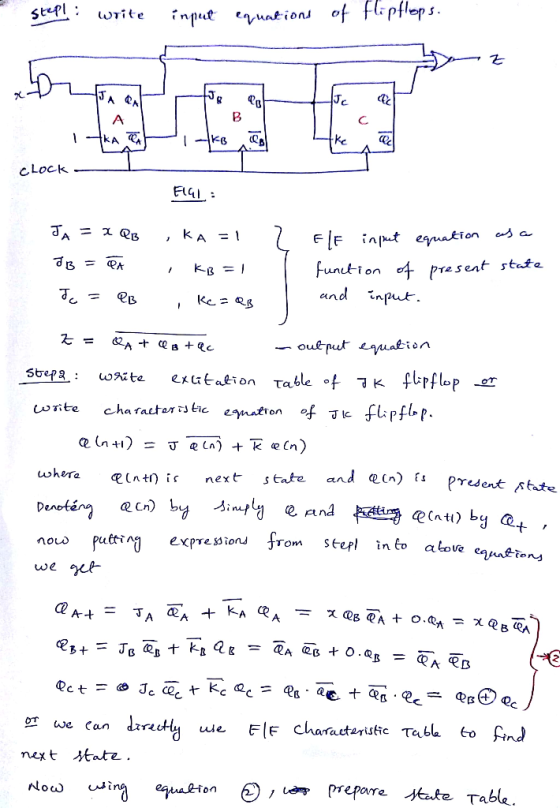
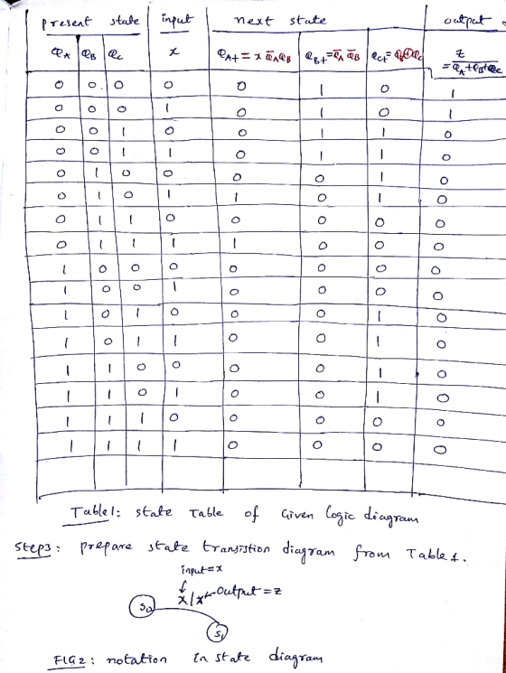
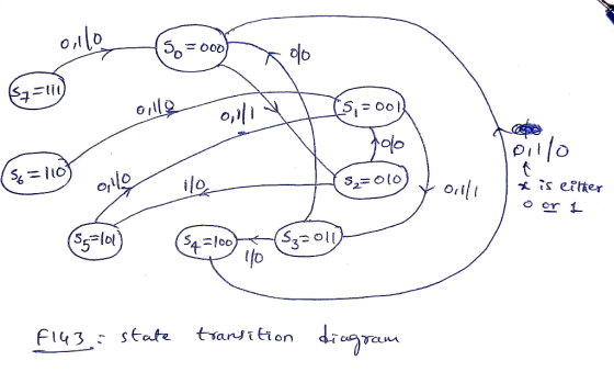
Show all steps C- For the following circuit, find the state and the outputs of the...
 Show all steps
C- For the following circuit, find the state and the outputs of the flip flops for three clocks. Assume that all flip flops are initially (A = 1, B = 1) and the input x = 0. Clock statc J-K flip flop J-K flip flop state A|A | state BB Initial state Clock Clock Clock
Show all steps
C- For the following circuit, find the state and the outputs of the flip flops for three clocks. Assume that all flip flops are initially (A = 1, B = 1) and the input x = 0. Clock statc J-K flip flop J-K flip flop state A|A | state BB Initial state Clock Clock Clock
 26. A counter is shown below. К, Q, К Q, CLOCK a. Find the state transition table and diagram. b. Show the count sequence. c. What is the mod of this counter? d. Modify this circuit so that it becomes self-starting, ie. it can enter the count sequence from any initial state. 13
26. A counter is shown below. К, Q, К Q, CLOCK a. Find the state transition table and diagram. b. Show the count sequence. c. What is...
26. A counter is shown below. К, Q, К Q, CLOCK a. Find the state transition table and diagram. b. Show the count sequence. c. What is the mod of this counter? d. Modify this circuit so that it becomes self-starting, ie. it can enter the count sequence from any initial state. 13
26. A counter is shown below. К, Q, К Q, CLOCK a. Find the state transition table and diagram. b. Show the count sequence. c. What is...
 Analyze the sequential counter
circuit shown in figure 5.1. Derive the state transition table and
diagram.
7400 U1 7400 01. 74x73 U2 4 74x13 76x73 Ly, QH122 7400 Reset (11) Clock - Figure 5.1
Analyze the sequential counter
circuit shown in figure 5.1. Derive the state transition table and
diagram.
7400 U1 7400 01. 74x73 U2 4 74x13 76x73 Ly, QH122 7400 Reset (11) Clock - Figure 5.1
 Write the state input and output equations, the state table, and the state diagram for the following circuit. Include at least one complete solution to each equation used to develop the truth table. K is connected to a logic high (1). Consider both CLK's to be connected to a proper external clock Also consider the PRE and CLR of each flip-flop to be connected to a logic high (1). 1. PRE PRE J Q K Q CLR dlo- CLR
Write...
Write the state input and output equations, the state table, and the state diagram for the following circuit. Include at least one complete solution to each equation used to develop the truth table. K is connected to a logic high (1). Consider both CLK's to be connected to a proper external clock Also consider the PRE and CLR of each flip-flop to be connected to a logic high (1). 1. PRE PRE J Q K Q CLR dlo- CLR
Write...
 Derive the input equations, state table and state diagram of
the following sequential
circuit.
2 2 Clock
Derive the input equations, state table and state diagram of
the following sequential
circuit.
2 2 Clock
 For the following sequential circuit, construct a transition
table and graph for the circuit. Attach files for both.
Forthe following sequential circuit, construct a transition table and graph for the circuit. Attach files for both. 7. B' CK J Clock Clock X" X" A B'
For the following sequential circuit, construct a transition
table and graph for the circuit. Attach files for both.
Forthe following sequential circuit, construct a transition table and graph for the circuit. Attach files for both. 7. B' CK J Clock Clock X" X" A B'
 17. The circuit below is given. Find the state table and diagram, Ap
17. The circuit below is given. Find the state table and diagram, Ap
17. The circuit below is given. Find the state table and diagram, Ap
 discrete math
a. For the finite state automaton given by the transition diagram, find the states, the input symbols, the initial state, the accepting states and write the annotated next-state table (inspired by Johnsonbaugh, 1997, p. 560). (4 marks) 02 (Johnsonbaugh, 1997, p. 560) a. Prove that k () = n(" - 1) for integers n and k with 1 Sks n, using a i. combinatorial proof; (3 marks) I ii. algebraic proof. (3 marks)
discrete math
a. For the finite state automaton given by the transition diagram, find the states, the input symbols, the initial state, the accepting states and write the annotated next-state table (inspired by Johnsonbaugh, 1997, p. 560). (4 marks) 02 (Johnsonbaugh, 1997, p. 560) a. Prove that k () = n(" - 1) for integers n and k with 1 Sks n, using a i. combinatorial proof; (3 marks) I ii. algebraic proof. (3 marks)
 Show all steps
C- For the following circuit, find the state and the outputs of the flip flops for three clocks. Assume that all flip flops are initially (A = 1, B = 1) and the input x = 0. Clock statc J-K flip flop J-K flip flop state A|A | state BB Initial state Clock Clock Clock
Show all steps
C- For the following circuit, find the state and the outputs of the flip flops for three clocks. Assume that all flip flops are initially (A = 1, B = 1) and the input x = 0. Clock statc J-K flip flop J-K flip flop state A|A | state BB Initial state Clock Clock Clock
Most questions answered within 3 hours.
-
An entomologist discovers a dung beetle rolling a ball of dung
along the ground, and decides...
asked 54 minutes ago -
Humans have used horses for transportation for millions of
years. Therefore, they will use horses for...
asked 2 hours ago -
The following are the Jensen Corporation's unit costs of making
and selling an item at a...
asked 3 hours ago -
Does direct Medicare reimbursement of Advanced practice nurses
increase access to their services?
asked 4 hours ago -
List and explain why a company would choose to use a
published
compensation survey vs. creating...
asked 4 hours ago -
A discrete random variable X can take values from 1 to 10. Find
the variance of...
asked 4 hours ago -
The primary financial goal of a corporation is to maximize:
shareholders wealth.
earnings per share.
stock...
asked 4 hours ago -
determine whether the vectors u=(1,2,3,), v=(-2,1,0) and
w=(1,0,1) are linearly dependent or independent.
asked 4 hours ago -
python
Define a function called print_values which takes a dictionary
object as a parameter. The function...
asked 5 hours ago -
In Chapter 1 you created a program named Triangle in
which you displayed a seven-line triangle...
asked 5 hours ago -
Research question: What are the differences between separately
stated and non separately stated transactions in an...
asked 6 hours ago -
By using Arduino write a code that connects two LEDs to two
push-buttons. Each button controls...
asked 7 hours ago