
Homework Answers
![LH + 6+ 7e uta 4) 5.2 ilt Ult) Laplace transform sta 2[ze btult) St6 - R L[R] => L [. SL ekt becomes A LS mm 13 * YOS 5 3 7 S](http://img.homeworklib.com/questions/b34b3950-8db0-11eb-b749-a5972e9a2610.png?x-oss-process=image/resize,w_560)
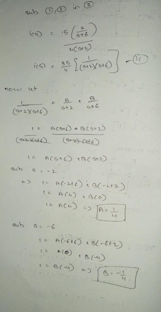
![becomes 35 + sta stb. { cs) 55+ [atz sto] med stor sto] - ics) 5 E apply inverse laplace transform on earl kav ieves) ma S (m](http://img.homeworklib.com/questions/b49c6610-8db0-11eb-ae75-c51472aec85a.png?x-oss-process=image/resize,w_560)
Add Answer to:
c) For the circuit shown in Figure 3, where u(t) is the unit step function, using...
HI, PLEASE ANSWER ALL PARTS AND PLEASE SHOW ALL WORKINGS STEP BY STEP. THANK YOU. Question...
 HI, PLEASE ANSWER ALL PARTS AND PLEASE SHOW ALL WORKINGS STEP BY STEP. THANK YOU. Question 1: a) Show from first principles that the Laplace transform of the function f(n)=1, 120 is f(s) = Make a note of any conditions imposed on the transform variable "s" to ensure the transform exists. (8 Marks) b) Find, using the appropriate theorem, the Laplace transform of a function f(t); b) f(t) = t.sin(56) OR ii) f(t) = 5 sin 2(t - 3). H(t...
Section 3: Laplace transform for RLC circuit analysis (10 marks) A second-order RLC circuit with a...
 Section 3: Laplace transform for RLC circuit analysis (10 marks) A second-order RLC circuit with a dependent source is shown in Fig. 3. 22 + VO - 132 1F + 15e-2 u(t) V ) 9[1-u(t)] V Y 0.50 » Fig. 3 A second-order RLC circuit with a dependent source Take the Laplace transform of the circuit and hence find the response io(t) for t > 0. Specify whether it is an underdamped, critically damped or overdamped case. Sketch the response.
Question 4 (a) Determine the Fourier transform of v(t) in the circuit shown in Figure 4...
 Question 4 (a) Determine the Fourier transform of v(t) in the circuit shown in Figure 4 below. (10 marks) 232 e-21u(t) V (+ + v(t) + IF ele 0.5H 28(1) A Figure 4 (b) For the network shown in Figure 5, by means of the Laplace Transform, evaluate i(t). (15 marks) 2e-fu(t) V + 1F io 1 H HI 112 WW 4u(t) A 122 Figure 5
Question 4. Refer to the circuit of Figure 4. R 802 50 uF с vi(t) v.(t)...
 Question 4. Refer to the circuit of Figure 4. R 802 50 uF с vi(t) v.(t) Figure 4 a) Draw the circuit in the Laplace domain, and then apply basic circuit theory in the Laplace domain to show that the Laplace transfer function H(s) defined for this system is: HS) V.(5) V (5) sta where a= RC [8 Marks] b) Use Laplace methods to determine the output voltage vo(t) when the input voltage is defined as: v (1) 40(1) The...
Exercise 4) Consider the RC network shown, where v(t) is the input voltage and ve(t) is...
 Exercise 4) Consider the RC network shown, where v(t) is the input voltage and ve(t) is the circuit output voltage. R is the same for all resistors (4a) Write differential equations of the circuit in terms of the currents. Convert the equa tions to the Laplace domain (5 marks)v(oO 4b) Find the transfer function Ve(s)/V(s) (5 marks) (4c) Using the final value theorem, calculate the steady-state value of ve(t) for an unit step input of u(t), i.e., u(t)-1 V (2.5...
System Modeling and Laplace transform: In this problem we will review the modeling proce- dure for the RLC circuit as shown below, and how to find the corresponding transfer function and step respons...
 System Modeling and Laplace transform: In this problem we will review the modeling proce- dure for the RLC circuit as shown below, and how to find the corresponding transfer function and step response Ri R2 Cv0) i2) i,(0) 3.1 Considering the input to be V(t) and the output to be Ve(t), find the transfer function of the system. To do that, first derive the differential equations for al the three loops and then take the Laplace transforms of them. 3.2...
please help. Note: u(t) is unit-step function Consider the system with the differential equation: dyt) +...
 please help.
Note: u(t) is unit-step function Consider the system with the differential equation: dyt) + 2 dy(t) + 2y(t) = dr(t) – r(e) dt2 dt where r(t) is input and y(t) is output. 1. Find the transfer function of the system. Note that transfer function is Laplace transform ratio of input and output under the assumption that all initial conditions are zero. 2. Find the impulse response of the system. 3. Find the unit step response of the system...
please help.
Note: u(t) is unit-step function Consider the system with the differential equation: dyt) + 2 dy(t) + 2y(t) = dr(t) – r(e) dt2 dt where r(t) is input and y(t) is output. 1. Find the transfer function of the system. Note that transfer function is Laplace transform ratio of input and output under the assumption that all initial conditions are zero. 2. Find the impulse response of the system. 3. Find the unit step response of the system...
1. Consider the circuit shown below. Cl e, (0) c, e。(t) Find the transfer function below using t...
 Please help with this dynamics circuit
analysis.
Please show work and explain.
Thank you!!
1. Consider the circuit shown below. Cl e, (0) c, e。(t) Find the transfer function below using time-domain and impedance methods. (a) Determine the differential equation for the relationship between eo(1) and e(1) (b) Find the transfer function E, (s)/E,(s) and determine the system time constant in terms of the circuit element values C, C, and R 17 2 (c) Find the transfer function E, (s)/E,...
Please help with this dynamics circuit
analysis.
Please show work and explain.
Thank you!!
1. Consider the circuit shown below. Cl e, (0) c, e。(t) Find the transfer function below using time-domain and impedance methods. (a) Determine the differential equation for the relationship between eo(1) and e(1) (b) Find the transfer function E, (s)/E,(s) and determine the system time constant in terms of the circuit element values C, C, and R 17 2 (c) Find the transfer function E, (s)/E,...
1 if t>0 Consider the unit step function u(t) if t0 0 if t< The Fourier transform of the unit ste...
 1 if t>0 Consider the unit step function u(t) if t0 0 if t< The Fourier transform of the unit step function is: U(ω)-Flu (t)]- πδ(w) + 1 , and the graph of the unit step function is shown below: u(t) 1/2 Relate intuitively each term of the Fourier transform U() given above to the corresponding parts f you find it helpful). Explain briefly below.
1 if t>0 Consider the unit step function u(t) if t0 0 if t
1 if t>0 Consider the unit step function u(t) if t0 0 if t< The Fourier transform of the unit step function is: U(ω)-Flu (t)]- πδ(w) + 1 , and the graph of the unit step function is shown below: u(t) 1/2 Relate intuitively each term of the Fourier transform U() given above to the corresponding parts f you find it helpful). Explain briefly below.
1 if t>0 Consider the unit step function u(t) if t0 0 if t
04 (2) A rectangular pulses, E (t) is applied to the RC circuit as shown in...
 04 (2) A rectangular pulses, E (t) is applied to the RC circuit as shown in Figure Q4(2). (1) Show that the circuit can be modelled as RC + V = (1) -4(-2) (ii) Calculate the response, or with C) = 0 ning Laplace transform. mark b) Consider the network circuit as shown in Figure Q4 (b) with initial current and their derivatives are zero fort = 0. 1) Show the loop current is can be formulated as dig dt...
 HI, PLEASE ANSWER ALL PARTS AND PLEASE SHOW ALL WORKINGS STEP BY STEP. THANK YOU. Question 1: a) Show from first principles that the Laplace transform of the function f(n)=1, 120 is f(s) = Make a note of any conditions imposed on the transform variable "s" to ensure the transform exists. (8 Marks) b) Find, using the appropriate theorem, the Laplace transform of a function f(t); b) f(t) = t.sin(56) OR ii) f(t) = 5 sin 2(t - 3). H(t...
 Section 3: Laplace transform for RLC circuit analysis (10 marks) A second-order RLC circuit with a dependent source is shown in Fig. 3. 22 + VO - 132 1F + 15e-2 u(t) V ) 9[1-u(t)] V Y 0.50 » Fig. 3 A second-order RLC circuit with a dependent source Take the Laplace transform of the circuit and hence find the response io(t) for t > 0. Specify whether it is an underdamped, critically damped or overdamped case. Sketch the response.
 Question 4 (a) Determine the Fourier transform of v(t) in the circuit shown in Figure 4 below. (10 marks) 232 e-21u(t) V (+ + v(t) + IF ele 0.5H 28(1) A Figure 4 (b) For the network shown in Figure 5, by means of the Laplace Transform, evaluate i(t). (15 marks) 2e-fu(t) V + 1F io 1 H HI 112 WW 4u(t) A 122 Figure 5
 Question 4. Refer to the circuit of Figure 4. R 802 50 uF с vi(t) v.(t) Figure 4 a) Draw the circuit in the Laplace domain, and then apply basic circuit theory in the Laplace domain to show that the Laplace transfer function H(s) defined for this system is: HS) V.(5) V (5) sta where a= RC [8 Marks] b) Use Laplace methods to determine the output voltage vo(t) when the input voltage is defined as: v (1) 40(1) The...
 Exercise 4) Consider the RC network shown, where v(t) is the input voltage and ve(t) is the circuit output voltage. R is the same for all resistors (4a) Write differential equations of the circuit in terms of the currents. Convert the equa tions to the Laplace domain (5 marks)v(oO 4b) Find the transfer function Ve(s)/V(s) (5 marks) (4c) Using the final value theorem, calculate the steady-state value of ve(t) for an unit step input of u(t), i.e., u(t)-1 V (2.5...
 System Modeling and Laplace transform: In this problem we will review the modeling proce- dure for the RLC circuit as shown below, and how to find the corresponding transfer function and step response Ri R2 Cv0) i2) i,(0) 3.1 Considering the input to be V(t) and the output to be Ve(t), find the transfer function of the system. To do that, first derive the differential equations for al the three loops and then take the Laplace transforms of them. 3.2...
 please help.
Note: u(t) is unit-step function Consider the system with the differential equation: dyt) + 2 dy(t) + 2y(t) = dr(t) – r(e) dt2 dt where r(t) is input and y(t) is output. 1. Find the transfer function of the system. Note that transfer function is Laplace transform ratio of input and output under the assumption that all initial conditions are zero. 2. Find the impulse response of the system. 3. Find the unit step response of the system...
please help.
Note: u(t) is unit-step function Consider the system with the differential equation: dyt) + 2 dy(t) + 2y(t) = dr(t) – r(e) dt2 dt where r(t) is input and y(t) is output. 1. Find the transfer function of the system. Note that transfer function is Laplace transform ratio of input and output under the assumption that all initial conditions are zero. 2. Find the impulse response of the system. 3. Find the unit step response of the system...
 Please help with this dynamics circuit
analysis.
Please show work and explain.
Thank you!!
1. Consider the circuit shown below. Cl e, (0) c, e。(t) Find the transfer function below using time-domain and impedance methods. (a) Determine the differential equation for the relationship between eo(1) and e(1) (b) Find the transfer function E, (s)/E,(s) and determine the system time constant in terms of the circuit element values C, C, and R 17 2 (c) Find the transfer function E, (s)/E,...
Please help with this dynamics circuit
analysis.
Please show work and explain.
Thank you!!
1. Consider the circuit shown below. Cl e, (0) c, e。(t) Find the transfer function below using time-domain and impedance methods. (a) Determine the differential equation for the relationship between eo(1) and e(1) (b) Find the transfer function E, (s)/E,(s) and determine the system time constant in terms of the circuit element values C, C, and R 17 2 (c) Find the transfer function E, (s)/E,...
 1 if t>0 Consider the unit step function u(t) if t0 0 if t< The Fourier transform of the unit step function is: U(ω)-Flu (t)]- πδ(w) + 1 , and the graph of the unit step function is shown below: u(t) 1/2 Relate intuitively each term of the Fourier transform U() given above to the corresponding parts f you find it helpful). Explain briefly below.
1 if t>0 Consider the unit step function u(t) if t0 0 if t
1 if t>0 Consider the unit step function u(t) if t0 0 if t< The Fourier transform of the unit step function is: U(ω)-Flu (t)]- πδ(w) + 1 , and the graph of the unit step function is shown below: u(t) 1/2 Relate intuitively each term of the Fourier transform U() given above to the corresponding parts f you find it helpful). Explain briefly below.
1 if t>0 Consider the unit step function u(t) if t0 0 if t
 04 (2) A rectangular pulses, E (t) is applied to the RC circuit as shown in Figure Q4(2). (1) Show that the circuit can be modelled as RC + V = (1) -4(-2) (ii) Calculate the response, or with C) = 0 ning Laplace transform. mark b) Consider the network circuit as shown in Figure Q4 (b) with initial current and their derivatives are zero fort = 0. 1) Show the loop current is can be formulated as dig dt...
Most questions answered within 3 hours.
-
How
would I know whether a given amino acid has an ionizable group or
not? please...
asked 1 minute ago -
True or false?
True False The function of the enzyme acyl CoA
synthetase is the ATP-dependent coupling...
asked 1 minute ago -
Nadia Corporation adjusts its debt so that its interest coverage
(EBIT/Interest) remains constant at 3. Nadia’s...
asked 3 minutes ago -
In a clinical trial, 20 out of 600 patients taking a
prescription drug complained of flulike...
asked 9 minutes ago -
7. How many types of nuclear processes can produce energy? 8.
How many types of radioactive...
asked 13 minutes ago -
For both the Sn2 and Sn1 reaction
conditions:
Structure | Rxn (Y/N) at room T° Rxn...
asked 14 minutes ago -
11. In cell N2, enter a formula using the IF function and a
structured reference to...
asked 13 minutes ago -
There is X-linked mutations in flies in this example. You need
to determine the inheritence pattern...
asked 15 minutes ago -
1) There is a 5.0 μC charge at each of 3 corners of a square
(each...
asked 26 minutes ago -
A study of 420,095 cell phone users found that
134 of them developed cancer of the...
asked 30 minutes ago -
2.50 g of NH4Cl is added to 12.9 g of water. Calculate the
molality of the...
asked 33 minutes ago -
Part 1
(a) Calculate the pH at 25°C of a 0.10 M solution of a
weak...
asked 34 minutes ago