
Homework Answers


Add Answer to:
04 (2) A rectangular pulses, E (t) is applied to the RC circuit as shown in...
c) For the circuit shown in Figure 3, where u(t) is the unit step function, using...
 c) For the circuit shown in Figure 3, where u(t) is the unit step function, using Laplace transform methods and showing all working, find the response i(t) fort> 0. (9 marks) 4H 7e-u(t) v(1) 352 322 Figure 3
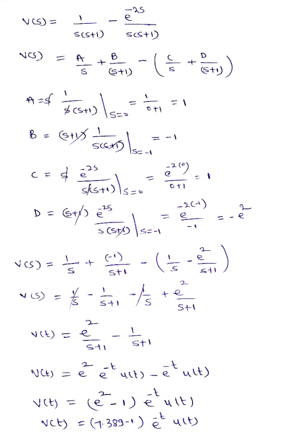
Question 4 (a) Determine the Fourier transform of v(t) in the circuit shown in Figure 4...
 Question 4 (a) Determine the Fourier transform of v(t) in the circuit shown in Figure 4 below. (10 marks) 232 e-21u(t) V (+ + v(t) + IF ele 0.5H 28(1) A Figure 4 (b) For the network shown in Figure 5, by means of the Laplace Transform, evaluate i(t). (15 marks) 2e-fu(t) V + 1F io 1 H HI 112 WW 4u(t) A 122 Figure 5
Part B. Please! Consider the circuit shown in Figure 2-1. (0) ist)) Figure 2-1 In the...
 Part B. Please!
Consider the circuit shown in Figure 2-1. (0) ist)) Figure 2-1 In the circuit above, L = 1m H and R = 3k 2. The input waveforms us (t) and is (t) are shown in Figure 2-2. us(t) is(t) IV 1 mA Figure 2-2 (a) Calculate the numerical value of the time constant , in micro-seconds (nus = 10-ºs). .33 (b) Assuming the network is at rest fort < 0, calculate the numerical value of the current...
Part B. Please!
Consider the circuit shown in Figure 2-1. (0) ist)) Figure 2-1 In the circuit above, L = 1m H and R = 3k 2. The input waveforms us (t) and is (t) are shown in Figure 2-2. us(t) is(t) IV 1 mA Figure 2-2 (a) Calculate the numerical value of the time constant , in micro-seconds (nus = 10-ºs). .33 (b) Assuming the network is at rest fort < 0, calculate the numerical value of the current...
(1) Consider the RC circuit shown in Figure 1. For t<0 the switch is open, and...
 (1) Consider the RC circuit shown in Figure 1. For t<0 the switch is open, and the charge stored on the capacitor is 0. At t-0 the switch is closed, and the voltage source begins charging the capacitor. Let R1-R2-220 Ω , C-0.47 μ F , Vs-5 V. (a) Write the differential equation as an expression for the capacitor voltage fort> 0 (i.e. write the differential equation) and calculate the time constant (b) Calculate the steady-state capacitor voltage R2 R1...
Problem 2 (35 points) In the circuit shown below, the switch is closed at t =...
 Problem 2 (35 points) In the circuit shown below, the switch is closed at t = 0. t=0 L = 1 mH C1 = 5 uF C2 = 10 uf = l(s) Problem 2 The capacitor voltages at t = 0 are VC, (0) VC, (0) = = -50 V 30 V where the capacitor voltage polarities are indicated on the circuit drawing. Solve for the loop current i(t) using the Laplace transform method.
10-76 The circuit in Figure P10-76 is shown in the t domain with initial values for...
 10-76 The circuit in Figure P10-76 is shown in the t domain with initial values for the energy storage devices. (a) Transform the circuit into the s domain and write a set of node-voltage equations. (b) Transform the circuit into the s domain and write a set of mesh-current equations. (c) With the circuit in the zero state, use symbolic operations in MATLAB to solve for the node voltages. UR ) R W Vol a ich Llo_c() W VAT) yp)...
Please answer clearly 2. Consider the circuit shown in Figure 1. Determine values of Ri, R2, and Rc to provide the quie...
 Please answer clearly
2. Consider the circuit shown in Figure 1. Determine values of Ri, R2, and Rc to provide the quiescent emitter current 1.5 mA and the quiescent collector to emitter voltage 5V. Assume β 100, Re-I㏀、Va= 200V, VBEon-0.7V, and VT= 25mV. R1 Rc Vcc に 10v R2 Re Figure 1: BJT biasing configuration
2. Consider the circuit shown in Figure 1. Determine values of Ri, R2, and Rc to provide the quiescent emitter current 1.5 mA and the...
Please answer clearly
2. Consider the circuit shown in Figure 1. Determine values of Ri, R2, and Rc to provide the quiescent emitter current 1.5 mA and the quiescent collector to emitter voltage 5V. Assume β 100, Re-I㏀、Va= 200V, VBEon-0.7V, and VT= 25mV. R1 Rc Vcc に 10v R2 Re Figure 1: BJT biasing configuration
2. Consider the circuit shown in Figure 1. Determine values of Ri, R2, and Rc to provide the quiescent emitter current 1.5 mA and the...
Question 1 For the circuit shown in figure 1; i. Find the transfer impedance function, H(s)...
 Question 1 For the circuit shown in figure 1; i. Find the transfer impedance function, H(s) = Vds(s) Find the poles and zeros for this transfer function and plot them on the s - Find the magnitude of the transfer function in decibels. [10] s-plane [8] ii [3] 2H 20 20 2 H Figure Question 2 The hybrid parameters (h-parameters) for the two -port network circuit in figure 2 are; 5 h=2 0.05 Find the equivalent impedance parameters (z-parameters) Find...
6.3 Exercises In Exercises 1-5 find the current in the RLC circuit, assuming that E(t) =...
 6.3 Exercises In Exercises 1-5 find the current in the RLC circuit, assuming that E(t) = 0 fort > 0. 1. R = 3 ohms; L = 1 henrysC = .01 farads; Q. = 0 coulombs, 10 = 2 amperes. 11. Show that if E(t) = U coswt +V sin wt where U and V are constants then the steady state current in the RLC circuit shown in Figure 6.3.1 is w?RE(t) + (1/C - Lw?) E' (t) I where...
Lab Procedure: Part 1: Source Free RC Circuit V(t) ilts C3 (R3 21ko 1uF IC=10V a)...
 Lab Procedure: Part 1: Source Free RC Circuit V(t) ilts C3 (R3 21ko 1uF IC=10V a) For the circuit shown above, provide the equation and calculate the following: 1. The source free equation for V(t) for V(O)= 10 volts 2. The equation for it) 3. V(t) and i(t) for t = t (one time constant) b) Now, enter the circuit using Multisim Schematic Capture. c) Simulate using Transient mode with a graphical output and verify graphical results with your calculations....
 c) For the circuit shown in Figure 3, where u(t) is the unit step function, using Laplace transform methods and showing all working, find the response i(t) fort> 0. (9 marks) 4H 7e-u(t) v(1) 352 322 Figure 3
 Question 4 (a) Determine the Fourier transform of v(t) in the circuit shown in Figure 4 below. (10 marks) 232 e-21u(t) V (+ + v(t) + IF ele 0.5H 28(1) A Figure 4 (b) For the network shown in Figure 5, by means of the Laplace Transform, evaluate i(t). (15 marks) 2e-fu(t) V + 1F io 1 H HI 112 WW 4u(t) A 122 Figure 5
 Part B. Please!
Consider the circuit shown in Figure 2-1. (0) ist)) Figure 2-1 In the circuit above, L = 1m H and R = 3k 2. The input waveforms us (t) and is (t) are shown in Figure 2-2. us(t) is(t) IV 1 mA Figure 2-2 (a) Calculate the numerical value of the time constant , in micro-seconds (nus = 10-ºs). .33 (b) Assuming the network is at rest fort < 0, calculate the numerical value of the current...
Part B. Please!
Consider the circuit shown in Figure 2-1. (0) ist)) Figure 2-1 In the circuit above, L = 1m H and R = 3k 2. The input waveforms us (t) and is (t) are shown in Figure 2-2. us(t) is(t) IV 1 mA Figure 2-2 (a) Calculate the numerical value of the time constant , in micro-seconds (nus = 10-ºs). .33 (b) Assuming the network is at rest fort < 0, calculate the numerical value of the current...
 (1) Consider the RC circuit shown in Figure 1. For t<0 the switch is open, and the charge stored on the capacitor is 0. At t-0 the switch is closed, and the voltage source begins charging the capacitor. Let R1-R2-220 Ω , C-0.47 μ F , Vs-5 V. (a) Write the differential equation as an expression for the capacitor voltage fort> 0 (i.e. write the differential equation) and calculate the time constant (b) Calculate the steady-state capacitor voltage R2 R1...
 Problem 2 (35 points) In the circuit shown below, the switch is closed at t = 0. t=0 L = 1 mH C1 = 5 uF C2 = 10 uf = l(s) Problem 2 The capacitor voltages at t = 0 are VC, (0) VC, (0) = = -50 V 30 V where the capacitor voltage polarities are indicated on the circuit drawing. Solve for the loop current i(t) using the Laplace transform method.
 10-76 The circuit in Figure P10-76 is shown in the t domain with initial values for the energy storage devices. (a) Transform the circuit into the s domain and write a set of node-voltage equations. (b) Transform the circuit into the s domain and write a set of mesh-current equations. (c) With the circuit in the zero state, use symbolic operations in MATLAB to solve for the node voltages. UR ) R W Vol a ich Llo_c() W VAT) yp)...
 Please answer clearly
2. Consider the circuit shown in Figure 1. Determine values of Ri, R2, and Rc to provide the quiescent emitter current 1.5 mA and the quiescent collector to emitter voltage 5V. Assume β 100, Re-I㏀、Va= 200V, VBEon-0.7V, and VT= 25mV. R1 Rc Vcc に 10v R2 Re Figure 1: BJT biasing configuration
2. Consider the circuit shown in Figure 1. Determine values of Ri, R2, and Rc to provide the quiescent emitter current 1.5 mA and the...
Please answer clearly
2. Consider the circuit shown in Figure 1. Determine values of Ri, R2, and Rc to provide the quiescent emitter current 1.5 mA and the quiescent collector to emitter voltage 5V. Assume β 100, Re-I㏀、Va= 200V, VBEon-0.7V, and VT= 25mV. R1 Rc Vcc に 10v R2 Re Figure 1: BJT biasing configuration
2. Consider the circuit shown in Figure 1. Determine values of Ri, R2, and Rc to provide the quiescent emitter current 1.5 mA and the...
 Question 1 For the circuit shown in figure 1; i. Find the transfer impedance function, H(s) = Vds(s) Find the poles and zeros for this transfer function and plot them on the s - Find the magnitude of the transfer function in decibels. [10] s-plane [8] ii [3] 2H 20 20 2 H Figure Question 2 The hybrid parameters (h-parameters) for the two -port network circuit in figure 2 are; 5 h=2 0.05 Find the equivalent impedance parameters (z-parameters) Find...
 6.3 Exercises In Exercises 1-5 find the current in the RLC circuit, assuming that E(t) = 0 fort > 0. 1. R = 3 ohms; L = 1 henrysC = .01 farads; Q. = 0 coulombs, 10 = 2 amperes. 11. Show that if E(t) = U coswt +V sin wt where U and V are constants then the steady state current in the RLC circuit shown in Figure 6.3.1 is w?RE(t) + (1/C - Lw?) E' (t) I where...
 Lab Procedure: Part 1: Source Free RC Circuit V(t) ilts C3 (R3 21ko 1uF IC=10V a) For the circuit shown above, provide the equation and calculate the following: 1. The source free equation for V(t) for V(O)= 10 volts 2. The equation for it) 3. V(t) and i(t) for t = t (one time constant) b) Now, enter the circuit using Multisim Schematic Capture. c) Simulate using Transient mode with a graphical output and verify graphical results with your calculations....
Most questions answered within 3 hours.
-
What are the variety of forms of products dispensed with aerosol
spray?
asked 1 minute ago -
Which one of the following statements is true about C++
keywords?
a. A keyword can have...
asked 1 minute ago -
Pyruvate Kinase, an allosteric enzyme, accelerates the
conversion of phosphoenolpyruvate to pyruvate.
1) Draw curves describing...
asked 3 minutes ago -
question 1
Which of the following is an example of a bottom-up technique
for developing promotional...
asked 21 minutes ago -
1)In FM modulation, what aspect of the carrier is being
modulated?
2)Explain in your own words,...
asked 17 minutes ago -
Andromeda Galaxy, M31, is considered a sister galaxy to Milky
Way galaxy. One similarirty is their...
asked 23 minutes ago -
How does temperature affect ADH during enzyme
kinetics?
asked 31 minutes ago -
A $1000 par value convertible bond has a conversion price of
$25. It is currently selling...
asked 39 minutes ago -
Write a java program that declares 10 element array (of type
integers), creates and initializes the...
asked 37 minutes ago -
import java.util.Arrays;
import java.util.Random;
import java.util.Scanner;
/**
* TODO Write a summary of the role of...
asked 42 minutes ago -
Sodium hydroxide is a strong base and ammonium hydroxide is a
weak base. Which of the...
asked 47 minutes ago -
Glycerol, C3H8O3, is a substance used extensively in the
manufacture of cosmetics, foodstuffs, antifreeze, and plastics....
asked 50 minutes ago