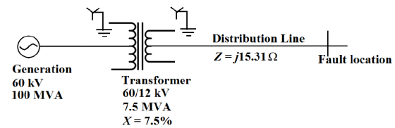
The diagram shows one phase of a 3-phase generation and distribution system. We would like to determine the 12 kV short circuit (maximum) current at the indicated location attributed to the generation, in the event of a fault.
For this question, we work in the per unit pu system.
a. We pick S(base)=100 MVA, and V(base) = 12 kV. Then I(base)
and Z(base) are fixed. The 12 kV of the transformer secondary is
line-neutral voltage since this is a grounded neutral voltage.
Converting the 12 kV to line-line voltage, show that I(base) =
4,811 A.
b. The distribution line impedance is referenced to the 12 kV
line-neutral voltage. Since impedance = (power/voltage2), show
that
Z(transmission line) = 10.6 pu on a 100 MVA base.
c. Taking Z(transformer) = 0.075 pu referenced to 7.5 MVA, show
that Z(transformer) =1.0 pu referenced to the 100 MVA base.
d. We can now convert I(base) to the short-circuit (maximum)
current at the fault location. This is I(base)/(total Z pu) = 415
A.
e. 100 MVA was chosen as S(base) but any value for S(base) could
have been chosen. Why?
This is a common type of calculation in the pu system. Note that
the 60 kV of the transformer primary did not matter in this
calculation, because the fault was in the 12 kV line
Homework Answers


Add Answer to:
The diagram shows one phase of a 3-phase generation and
distribution system. We would like to...
The one-line diagram of a simple power system is shown in Figure 1. The neutral of...
 The one-line diagram of a simple power system is shown in Figure 1. The neutral of each generator is grounded through a current-limiting reactor of 0.25/3 per unit on a 100-MVA base. The system data expressed in per unit on a common 100-MVA base is tabulated below. The generators are running on no-load at their rated voltage and rated frequency with their emfs in phase. Determine the fault current for the following faults giving Zo = 0.35, Z = 0.22...
A single line diagram of a power system is shown in Fig. 2. The system data with equipment ratings and assumed sequence reactances are given the following table. The neutrals of the generator and A-Y...
 A single line diagram of a power system is shown in Fig. 2. The system data with equipment ratings and assumed sequence reactances are given the following table. The neutrals of the generator and A-Y transformers are solidly grounded. The motor neutral is grounded through a reactance Xn 0.05 per unit on the motor base. Assume that Pre-fault voltage is takin as VF-1.0 ,0° per unit and Pre- fault load current and Δ-Y transformer phase shift are neglected In the...
Fig Qshows the one-line diagram of a three-phase power system. As shown in Fig. Q3. the...
 Fig Qshows the one-line diagram of a three-phase power system.
As shown in Fig. Q3. the two zones are connected by a 400 MVA,
240-kV/24-kV, Ý-A three phase transformer. The Y-A three phase
transfonmer has an equivalent series impedance of ZTH - 1.2 + j1.6n
per phase referred to the high voltage side (primary side). The
three-phase power system can be studied with per unit quantities
using base values of S-500 MVA and 240 kV in zone 1.
By using...
Fig Qshows the one-line diagram of a three-phase power system.
As shown in Fig. Q3. the two zones are connected by a 400 MVA,
240-kV/24-kV, Ý-A three phase transformer. The Y-A three phase
transfonmer has an equivalent series impedance of ZTH - 1.2 + j1.6n
per phase referred to the high voltage side (primary side). The
three-phase power system can be studied with per unit quantities
using base values of S-500 MVA and 240 kV in zone 1.
By using...
Bus A Bus B R1 TI ine 1 20% 80% line 2 T2 R2 110 kV 11 kV The fault is located at point F, which ...
 Bus A Bus B R1 TI ine 1 20% 80% line 2 T2 R2 110 kV 11 kV The fault is located at point F, which is 20% of the total line 2 length from Bus B Fault MVA 1524.20471 Three-phase fault level in MVA at bus A SPFL (kA) 8 MVA1 MVA2 X1 (96 X2 (96) R1 (2) R2 (Q) z' (Q) Zo (2) Rf (Q) Single phase to ground fault level (kA) at bus A Transformer 1 MVA...
Fig. Q3 shows the one-line diagram of a three-phase power system. As shown in Fig. 23,...
 Fig. Q3 shows the one-line diagram of a three-phase power system. As shown in Fig. 23, the two zones are connected by a 400 MVA, 240-kV/24-kV, Y-A three phase transformer. The Y-three phase transformer has an equivalent series impedance of 2T - 1.2 + |1.6 per phase referred to the high-voltage side (primary side). The three-phase power system can be studied with per unit quantities using base values of So=500 MVA and 240 kV in zone 1. 2 -1.61253.15" Line...
(30) Assume that a distribution substation, shown below, has a 4000 kVA 69/12.47 kV LTC 4)...
 (30) Assume that a distribution substation, shown below, has a 4000 kVA 69/12.47 kV LTC 4) transformer feeding a three-phase four-wire 12.47 kV distribution system. The transformer has a reactance of 0.065 pu. Assume that fault impedance is 40 Q and that the maximum and minimum power generations of the system are 600 and 360 MVA, respectively. Use 1 MVA as the three-phase power base: a) Under the maximum (system) power generation conditions, determine the available three- phase, L-L, and...
3) The single-line diagram of a three-phase power system is shown in Fig. 1. Equipment ratings...
 3) The single-line diagram of a three-phase power system is shown in Fig. 1. Equipment ratings are given as follows: G1 1,000 MVA, 15.0 kV, 20.18, o 0.07 pu G2 : 1,000 MVA. 15.0 kV, 攻=エ1 =エ2 = 0.20, ro = 0.10 pu G3 : 500 MVA, 13.8 kV. 1" = 띠 z2 = 0.15, zo 0.05 pu G4 : 750 MVA, 13.8 kV. ェd =ェ1 = 0.30, T2 = 0.40 ro = 0.10 pu Ti : 1,000 MVA. 15.0Δ/765Y...
Bus A Bus B R1 TI ine 1 20% 80% line 2 T2 R2 110 kV 11 kV The fault is located at point F, which ...
 Bus A Bus B R1 TI ine 1 20% 80% line 2 T2 R2 110 kV 11 kV The fault is located at point F, which is 20% of the total line 2 length from Bus B Fault MVA 1524.20471 Three-phase fault level in MVA at bus A SPFL (kA) 8 MVA1 MVA2 X1 (96 X2 (96) R1 (2) R2 (Q) z' (Q) Zo (2) Rf (Q) Single phase to ground fault level (kA) at bus A Transformer 1 MVA...
Bus A Bus B R1 T1 line 1 20% 80% line 2 T2 R2 110 kV 11 kV The fault is located at point F, which...
 Bus A Bus B R1 T1 line 1 20% 80% line 2 T2 R2 110 kV 11 kV The fault is located at point F, which is 20% of the total line 2 length from Bus B Fault MVA 1524.20471 Three-phase fault level in MVA at bus A SPFL (kA) 8 MVA1 MVA2 X1 (96) X2 (96) R1 (2) R2 (Q) z' (Q) Zo (2) Rf (Q) Single phase to ground fault level (kA) at bus A Transformer 1 MVA...
 The one-line diagram of a simple power system is shown in Figure 1. The neutral of each generator is grounded through a current-limiting reactor of 0.25/3 per unit on a 100-MVA base. The system data expressed in per unit on a common 100-MVA base is tabulated below. The generators are running on no-load at their rated voltage and rated frequency with their emfs in phase. Determine the fault current for the following faults giving Zo = 0.35, Z = 0.22...
 A single line diagram of a power system is shown in Fig. 2. The system data with equipment ratings and assumed sequence reactances are given the following table. The neutrals of the generator and A-Y transformers are solidly grounded. The motor neutral is grounded through a reactance Xn 0.05 per unit on the motor base. Assume that Pre-fault voltage is takin as VF-1.0 ,0° per unit and Pre- fault load current and Δ-Y transformer phase shift are neglected In the...
 Fig Qshows the one-line diagram of a three-phase power system.
As shown in Fig. Q3. the two zones are connected by a 400 MVA,
240-kV/24-kV, Ý-A three phase transformer. The Y-A three phase
transfonmer has an equivalent series impedance of ZTH - 1.2 + j1.6n
per phase referred to the high voltage side (primary side). The
three-phase power system can be studied with per unit quantities
using base values of S-500 MVA and 240 kV in zone 1.
By using...
Fig Qshows the one-line diagram of a three-phase power system.
As shown in Fig. Q3. the two zones are connected by a 400 MVA,
240-kV/24-kV, Ý-A three phase transformer. The Y-A three phase
transfonmer has an equivalent series impedance of ZTH - 1.2 + j1.6n
per phase referred to the high voltage side (primary side). The
three-phase power system can be studied with per unit quantities
using base values of S-500 MVA and 240 kV in zone 1.
By using...
 Bus A Bus B R1 TI ine 1 20% 80% line 2 T2 R2 110 kV 11 kV The fault is located at point F, which is 20% of the total line 2 length from Bus B Fault MVA 1524.20471 Three-phase fault level in MVA at bus A SPFL (kA) 8 MVA1 MVA2 X1 (96 X2 (96) R1 (2) R2 (Q) z' (Q) Zo (2) Rf (Q) Single phase to ground fault level (kA) at bus A Transformer 1 MVA...
 Fig. Q3 shows the one-line diagram of a three-phase power system. As shown in Fig. 23, the two zones are connected by a 400 MVA, 240-kV/24-kV, Y-A three phase transformer. The Y-three phase transformer has an equivalent series impedance of 2T - 1.2 + |1.6 per phase referred to the high-voltage side (primary side). The three-phase power system can be studied with per unit quantities using base values of So=500 MVA and 240 kV in zone 1. 2 -1.61253.15" Line...
 (30) Assume that a distribution substation, shown below, has a 4000 kVA 69/12.47 kV LTC 4) transformer feeding a three-phase four-wire 12.47 kV distribution system. The transformer has a reactance of 0.065 pu. Assume that fault impedance is 40 Q and that the maximum and minimum power generations of the system are 600 and 360 MVA, respectively. Use 1 MVA as the three-phase power base: a) Under the maximum (system) power generation conditions, determine the available three- phase, L-L, and...
 (30) Assume that a distribution substation, shown below, has a 4000 kVA 69/12.47 kV LTC 4) transformer feeding a three-phase four-wire 12.47 kV distribution system. The transformer has a reactance of 0.065 pu. Assume that fault impedance is 40 Q and that the maximum and minimum power generations of the system are 600 and 360 MVA, respectively. Use 1 MVA as the three-phase power base: a) Under the maximum (system) power generation conditions, determine the available three- phase, L-L, and...
 3) The single-line diagram of a three-phase power system is shown in Fig. 1. Equipment ratings are given as follows: G1 1,000 MVA, 15.0 kV, 20.18, o 0.07 pu G2 : 1,000 MVA. 15.0 kV, 攻=エ1 =エ2 = 0.20, ro = 0.10 pu G3 : 500 MVA, 13.8 kV. 1" = 띠 z2 = 0.15, zo 0.05 pu G4 : 750 MVA, 13.8 kV. ェd =ェ1 = 0.30, T2 = 0.40 ro = 0.10 pu Ti : 1,000 MVA. 15.0Δ/765Y...
 Bus A Bus B R1 TI ine 1 20% 80% line 2 T2 R2 110 kV 11 kV The fault is located at point F, which is 20% of the total line 2 length from Bus B Fault MVA 1524.20471 Three-phase fault level in MVA at bus A SPFL (kA) 8 MVA1 MVA2 X1 (96 X2 (96) R1 (2) R2 (Q) z' (Q) Zo (2) Rf (Q) Single phase to ground fault level (kA) at bus A Transformer 1 MVA...
 Bus A Bus B R1 T1 line 1 20% 80% line 2 T2 R2 110 kV 11 kV The fault is located at point F, which is 20% of the total line 2 length from Bus B Fault MVA 1524.20471 Three-phase fault level in MVA at bus A SPFL (kA) 8 MVA1 MVA2 X1 (96) X2 (96) R1 (2) R2 (Q) z' (Q) Zo (2) Rf (Q) Single phase to ground fault level (kA) at bus A Transformer 1 MVA...
Most questions answered within 3 hours.
-
For this problem, carry at least four digits after the decimal
in your calculations. Answers may...
asked 3 hours ago -
Ask a user for three positive integer numbers. Use an input
validation loop to make sure...
asked 3 hours ago -
The most primitive form of data from data analysis perspective
is a. nominal scale b. ordinal...
asked 3 hours ago -
The number of vacancies in some hypothetical metal increases by
a factor of 5 when the...
asked 3 hours ago -
The fiduciary duty that is predicated on the concept that a
board of directors and officers...
asked 3 hours ago -
Sustainable Growth Rate Last year Umbrellas Unlimited
Corporation had an ROE of 17.3% and a dividend...
asked 3 hours ago -
Write a MATLAB program to do the following:
Receive 5 input values and store them into...
asked 3 hours ago -
Which one of the following aqueous solutions would you expect to
have the largest conductance: (a)...
asked 3 hours ago -
(Intermediate Macroeconomics)
2.The aggregate supply function be ys=2000+P, and the aggregate
demand function be yD=2400-P。Find the...
asked 3 hours ago -
I am having a really difficult time developing a strong thesis
for this question....... To what...
asked 3 hours ago -
There are n street lights in a line. In order to conserve
energy, the city decides...
asked 3 hours ago -
Cellular growth and repair require a cell to go through the cell
cycle. Like all biological...
asked 3 hours ago