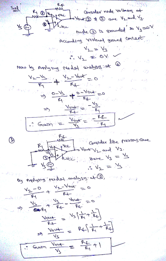
Using the two rules formulated in introduction, derive the expressions for the voltage gains for the inverting (Figures 2) and noninverting (Figure 3) amplifiers

Homework Answers
Rate my answer if you are satisfied with the solution
Thank you
Add Answer to:
Using the two rules formulated in introduction, derive the
expressions for the voltage gains for the...
i)draw the transafer charcheristics for this circuit? ii)Derive expressions for VTH and VTL? iii)Let L+ = - L- = 10 V, and R1=1 k Ω , choose R2 in order to get a hysteresis of 100mV width? iv).An engi...
 i)draw the transafer
charcheristics for this circuit?
ii)Derive expressions for VTH and VTL?
iii)Let L+ = - L- = 10 V, and R1=1 k Ω , choose R2 in order to
get a hysteresis of
100mV width?
iv).An engineer decided to modify the given circuit by
disconnecting the inverting
input of the op-amp from the ground and connecting it to a constant
voltage
source Vx. Derive expressions for VTH and VTL and Draw the transfer
characteristics in this case.?
Question...
i)draw the transafer
charcheristics for this circuit?
ii)Derive expressions for VTH and VTL?
iii)Let L+ = - L- = 10 V, and R1=1 k Ω , choose R2 in order to
get a hysteresis of
100mV width?
iv).An engineer decided to modify the given circuit by
disconnecting the inverting
input of the op-amp from the ground and connecting it to a constant
voltage
source Vx. Derive expressions for VTH and VTL and Draw the transfer
characteristics in this case.?
Question...
Problem 2.2 Using the same methods shown in lecture, mathematically derive: (a) The voltage conversion ratio equat...
 Problem 2.2 Using the same methods shown in lecture, mathematically derive: (a) The voltage conversion ratio equationwhen the Buck-Boost is operating in Discontinuous Conduction Mode (DCM). Your answer should be a function of D, Ro, T, and L (b) The value of the inductor discharge duty cycle coefficient; D1.Your answer should be a function of Ro, T, and L. Hint 1: Other than assessing the current waveforms, you will also need to apply the assumption of 100% efficiency from Problem...
• For the circuit in Figure 1, assume that the voltage drop across the infrared emitter...
 • For the circuit in Figure 1, assume that the voltage drop
across the infrared emitter is 1.3 V. Determine the value of RE
that will limit the emitter current to a maximum of 50 mA.
• For the circuit in Figure 1, assume RX = 10 kΩ and VS = 5 V.
Using the equation given in the introduction section, determine the
value of RF needed to implement the Schmitt Trigger with a spread
or hysteresis value between 0.5...
• For the circuit in Figure 1, assume that the voltage drop
across the infrared emitter is 1.3 V. Determine the value of RE
that will limit the emitter current to a maximum of 50 mA.
• For the circuit in Figure 1, assume RX = 10 kΩ and VS = 5 V.
Using the equation given in the introduction section, determine the
value of RF needed to implement the Schmitt Trigger with a spread
or hysteresis value between 0.5...
Problem 2.2 Using the same methods shown in lecture, mathematically derive: (a) The voltage conversion ratio...
 Problem 2.2 Using the same methods shown in lecture, mathematically derive: (a) The voltage conversion ratio equationwhen the Buck-Boost is operating in Discontinuous Conduction Mode (DCM). Your answer should be a function of D, Ro, T, and L (b) The value of the inductor discharge duty cycle coefficient; D1.Your answer should be a function of Ro, T, and L. Hint 1: Other than assessing the current waveforms, you will also need to apply the assumption of 100% efficiency from Problem...
QUESTION 2 (15 Points) You are asked to design an electronic circuit using operational amplifiers. There are two inputs...
 QUESTION 2 You are asked to design an electronic circuit using operational amplifiers. There are two inputs to the circuit, \(V_{1}=0.1 \sin 100 t V\), and \(V_{2}=0.25 \cos 250 \pi t V\). The output of the circuit is required to be:$$ V_{0}=-\sin 100 t+5 \cos 250 \pi t V $$a. Draw diagram of the circuit you designed.b. Calculate the values of the components.QUESTION 3 An inverting circuit is shown in the figure.a. Derive an expression for \( v_{x} / v_{1}\)b. Derive an expression...
Problem 9.14 2 of 13 Review I Constants The expressions for the steady-state voltage and current...
 Problem 9.14 2 of 13 Review I Constants The expressions for the steady-state voltage and current at the terminals of the circuit seen in the figure are g 350 cos(5000xt85°) V, ig=8 sin(5000rt 108°) A (Figure 1) Part A What is the impedance seen by the source? Express your answer in ohms to three significant figures using polar notation. Express argument in degrees. VA D T vec Z=43.75 27 Ω Previous Answers Request Answer Submit Incorrect; Try Again; 3 attempts...
Laboratory 1: operation amplifier characteristics A. Objectives: 1. To study the basic characteri...
 thanks
Laboratory 1: operation amplifier characteristics A. Objectives: 1. To study the basic characteristics of an operational amplifier 2. To study the bias circuit of an operational amplifier B. Apparatus: 1. DC Power supply 2. Experimental board and corresponding components 3. Electronic calculator (prepared by students) 4. Digital camera (prepared by students for photo taking of the experimental results) 5. Laptop computer with the software PicoScope 6 and Microsoft Word installed. 6. PicoScope PC Oscilloscope and its accessories. 7. Multimeter...
thanks
Laboratory 1: operation amplifier characteristics A. Objectives: 1. To study the basic characteristics of an operational amplifier 2. To study the bias circuit of an operational amplifier B. Apparatus: 1. DC Power supply 2. Experimental board and corresponding components 3. Electronic calculator (prepared by students) 4. Digital camera (prepared by students for photo taking of the experimental results) 5. Laptop computer with the software PicoScope 6 and Microsoft Word installed. 6. PicoScope PC Oscilloscope and its accessories. 7. Multimeter...
I would like the values for the table Experiment I. 2. Build the DC Inverting Amplifier...
 I would like the values for the table
Experiment I. 2. Build the DC Inverting Amplifier with RI-22K R2=100K For the lab, we can utilize the breadboard optimally by plugging the Op-Amp into the breadboard so that it straddles the gap between the top and bottom sections of the socket strip, which is shown in Fig. P.5 Output 741 +Input Fig. P.5. Op-Amp Positioning on Breadboard. 3. Sct the Power Source CHI and CH2 to 15 V a. Ensure the...
I would like the values for the table
Experiment I. 2. Build the DC Inverting Amplifier with RI-22K R2=100K For the lab, we can utilize the breadboard optimally by plugging the Op-Amp into the breadboard so that it straddles the gap between the top and bottom sections of the socket strip, which is shown in Fig. P.5 Output 741 +Input Fig. P.5. Op-Amp Positioning on Breadboard. 3. Sct the Power Source CHI and CH2 to 15 V a. Ensure the...
For the circuit in Figure 1, assme that the voltage drop across the infrared emitter is 1.3 V. De...
 R1= 12 K ohm
R2= 12 K ohm
rout= 1.2 K ohm
For the circuit in Figure 1, assme that the voltage drop across the infrared emitter is 1.3 V. Determine the value of RE that will set the current through the emitter to a value within the range of 50 mA to 80 mA. For the circuit in Figure 1, assume Rx 10 kQ and Vs 5 V. Using the equation given in the introduction section, determine the value...
R1= 12 K ohm
R2= 12 K ohm
rout= 1.2 K ohm
For the circuit in Figure 1, assme that the voltage drop across the infrared emitter is 1.3 V. Determine the value of RE that will set the current through the emitter to a value within the range of 50 mA to 80 mA. For the circuit in Figure 1, assume Rx 10 kQ and Vs 5 V. Using the equation given in the introduction section, determine the value...
Exercise #4 Voltage Divider A. Introduction In a previous exercise, you learned about the current-voltage relationship...
 Exercise #4 Voltage Divider A. Introduction In a previous exercise, you learned about the current-voltage relationship in a single resistor. Now, you will about how voltage is divided across two resistors in series. In this exercise you will: Examine the operation of the electric circuit known as the voltape divicder At the conclusion of this exercise you should be able to Compute the valtage across a resistor in a voltage divider circuit Design a voltage divider circuit to produce a...
 i)draw the transafer
charcheristics for this circuit?
ii)Derive expressions for VTH and VTL?
iii)Let L+ = - L- = 10 V, and R1=1 k Ω , choose R2 in order to
get a hysteresis of
100mV width?
iv).An engineer decided to modify the given circuit by
disconnecting the inverting
input of the op-amp from the ground and connecting it to a constant
voltage
source Vx. Derive expressions for VTH and VTL and Draw the transfer
characteristics in this case.?
Question...
i)draw the transafer
charcheristics for this circuit?
ii)Derive expressions for VTH and VTL?
iii)Let L+ = - L- = 10 V, and R1=1 k Ω , choose R2 in order to
get a hysteresis of
100mV width?
iv).An engineer decided to modify the given circuit by
disconnecting the inverting
input of the op-amp from the ground and connecting it to a constant
voltage
source Vx. Derive expressions for VTH and VTL and Draw the transfer
characteristics in this case.?
Question...
 Problem 2.2 Using the same methods shown in lecture, mathematically derive: (a) The voltage conversion ratio equationwhen the Buck-Boost is operating in Discontinuous Conduction Mode (DCM). Your answer should be a function of D, Ro, T, and L (b) The value of the inductor discharge duty cycle coefficient; D1.Your answer should be a function of Ro, T, and L. Hint 1: Other than assessing the current waveforms, you will also need to apply the assumption of 100% efficiency from Problem...
 • For the circuit in Figure 1, assume that the voltage drop
across the infrared emitter is 1.3 V. Determine the value of RE
that will limit the emitter current to a maximum of 50 mA.
• For the circuit in Figure 1, assume RX = 10 kΩ and VS = 5 V.
Using the equation given in the introduction section, determine the
value of RF needed to implement the Schmitt Trigger with a spread
or hysteresis value between 0.5...
• For the circuit in Figure 1, assume that the voltage drop
across the infrared emitter is 1.3 V. Determine the value of RE
that will limit the emitter current to a maximum of 50 mA.
• For the circuit in Figure 1, assume RX = 10 kΩ and VS = 5 V.
Using the equation given in the introduction section, determine the
value of RF needed to implement the Schmitt Trigger with a spread
or hysteresis value between 0.5...
 Problem 2.2 Using the same methods shown in lecture, mathematically derive: (a) The voltage conversion ratio equationwhen the Buck-Boost is operating in Discontinuous Conduction Mode (DCM). Your answer should be a function of D, Ro, T, and L (b) The value of the inductor discharge duty cycle coefficient; D1.Your answer should be a function of Ro, T, and L. Hint 1: Other than assessing the current waveforms, you will also need to apply the assumption of 100% efficiency from Problem...
 QUESTION 2 You are asked to design an electronic circuit using operational amplifiers. There are two inputs to the circuit, \(V_{1}=0.1 \sin 100 t V\), and \(V_{2}=0.25 \cos 250 \pi t V\). The output of the circuit is required to be:$$ V_{0}=-\sin 100 t+5 \cos 250 \pi t V $$a. Draw diagram of the circuit you designed.b. Calculate the values of the components.QUESTION 3 An inverting circuit is shown in the figure.a. Derive an expression for \( v_{x} / v_{1}\)b. Derive an expression...
 Problem 9.14 2 of 13 Review I Constants The expressions for the steady-state voltage and current at the terminals of the circuit seen in the figure are g 350 cos(5000xt85°) V, ig=8 sin(5000rt 108°) A (Figure 1) Part A What is the impedance seen by the source? Express your answer in ohms to three significant figures using polar notation. Express argument in degrees. VA D T vec Z=43.75 27 Ω Previous Answers Request Answer Submit Incorrect; Try Again; 3 attempts...
 thanks
Laboratory 1: operation amplifier characteristics A. Objectives: 1. To study the basic characteristics of an operational amplifier 2. To study the bias circuit of an operational amplifier B. Apparatus: 1. DC Power supply 2. Experimental board and corresponding components 3. Electronic calculator (prepared by students) 4. Digital camera (prepared by students for photo taking of the experimental results) 5. Laptop computer with the software PicoScope 6 and Microsoft Word installed. 6. PicoScope PC Oscilloscope and its accessories. 7. Multimeter...
thanks
Laboratory 1: operation amplifier characteristics A. Objectives: 1. To study the basic characteristics of an operational amplifier 2. To study the bias circuit of an operational amplifier B. Apparatus: 1. DC Power supply 2. Experimental board and corresponding components 3. Electronic calculator (prepared by students) 4. Digital camera (prepared by students for photo taking of the experimental results) 5. Laptop computer with the software PicoScope 6 and Microsoft Word installed. 6. PicoScope PC Oscilloscope and its accessories. 7. Multimeter...
 I would like the values for the table
Experiment I. 2. Build the DC Inverting Amplifier with RI-22K R2=100K For the lab, we can utilize the breadboard optimally by plugging the Op-Amp into the breadboard so that it straddles the gap between the top and bottom sections of the socket strip, which is shown in Fig. P.5 Output 741 +Input Fig. P.5. Op-Amp Positioning on Breadboard. 3. Sct the Power Source CHI and CH2 to 15 V a. Ensure the...
I would like the values for the table
Experiment I. 2. Build the DC Inverting Amplifier with RI-22K R2=100K For the lab, we can utilize the breadboard optimally by plugging the Op-Amp into the breadboard so that it straddles the gap between the top and bottom sections of the socket strip, which is shown in Fig. P.5 Output 741 +Input Fig. P.5. Op-Amp Positioning on Breadboard. 3. Sct the Power Source CHI and CH2 to 15 V a. Ensure the...
 R1= 12 K ohm
R2= 12 K ohm
rout= 1.2 K ohm
For the circuit in Figure 1, assme that the voltage drop across the infrared emitter is 1.3 V. Determine the value of RE that will set the current through the emitter to a value within the range of 50 mA to 80 mA. For the circuit in Figure 1, assume Rx 10 kQ and Vs 5 V. Using the equation given in the introduction section, determine the value...
R1= 12 K ohm
R2= 12 K ohm
rout= 1.2 K ohm
For the circuit in Figure 1, assme that the voltage drop across the infrared emitter is 1.3 V. Determine the value of RE that will set the current through the emitter to a value within the range of 50 mA to 80 mA. For the circuit in Figure 1, assume Rx 10 kQ and Vs 5 V. Using the equation given in the introduction section, determine the value...
 Exercise #4 Voltage Divider A. Introduction In a previous exercise, you learned about the current-voltage relationship in a single resistor. Now, you will about how voltage is divided across two resistors in series. In this exercise you will: Examine the operation of the electric circuit known as the voltape divicder At the conclusion of this exercise you should be able to Compute the valtage across a resistor in a voltage divider circuit Design a voltage divider circuit to produce a...
Most questions answered within 3 hours.
-
10. Complete the table below
only using hexadecimal numbers:
AL CODE
EBX
EAX
[EAX]
mov eax,...
asked 9 minutes ago -
trust is best established through the combination of ------and
------- .
1. magnanimity and justice
2....
asked 24 minutes ago -
Blood pressure is normally taken on the upper arm at the level
of the heart. Suppose,...
asked 23 minutes ago -
Suppose that the satellite around the earth has an orbit that is
24 KM larger in...
asked 26 minutes ago -
Calculate the [OH (aq)] in limes which have a [H3O*(aq)] of 1.3 x
10 mol/L
asked 24 minutes ago -
A nozzle with a radius of 0.250 cm is attached to a garden hose
with a...
asked 35 minutes ago -
PLEASE do not use any loops for the program; only recursion is
allowed
4. Write a...
asked 44 minutes ago -
Please help me with me. I did the first part to write the operations but in...
asked 41 minutes ago -
Use Cryptool to find the Cryptographic SHA-1 hash value of the
string "abc". The calculator is...
asked 45 minutes ago -
You are attempting to calculate a firm’s free cash flow to
equity. You know the following...
asked 1 hour ago -
the following reaction occurs in a balloon containing
N2O2 gas
N2O4(g)=2NO2(g)
will the volume of the...
asked 2 hours ago -
answer the questions throughout this program
public class Day implements Comparable {
Private Boolean atWork;...
asked 2 hours ago