
Homework Answers


Add Answer to:
I have very little time please can you solve it urgently.
Thank you.
3.) Consider the...
please help to solve . Thank you A4. What is time response of the control system?...
 please help to solve . Thank you
A4. What is time response of the control system? (around 50 words) (5 marks) A5. A unity feedback system has Open loop Transfer system (s+1). What is its Closed loop Transfer function? (5 marks) A6. A unity feedback system has Open loop Transfer system s/(s+1). What is its Closed loop Transfer function? (5 marks)
please help to solve . Thank you
A4. What is time response of the control system? (around 50 words) (5 marks) A5. A unity feedback system has Open loop Transfer system (s+1). What is its Closed loop Transfer function? (5 marks) A6. A unity feedback system has Open loop Transfer system s/(s+1). What is its Closed loop Transfer function? (5 marks)
I have no more posting for this month, please solve these for me thanks 1. Given...
 I have no more posting for this month, please solve these for me
thanks
1. Given the following unity feedback system where s+z s2 (s + 10) and the controller is a proportional controller Ge = K, do the following: a. If z = 2, find K so that the damped frequency of the oscillation of the transient response is 5 rad/s. b. The system is to be redesigned by changing the values of z and K. If the new...
I have no more posting for this month, please solve these for me
thanks
1. Given the following unity feedback system where s+z s2 (s + 10) and the controller is a proportional controller Ge = K, do the following: a. If z = 2, find K so that the damped frequency of the oscillation of the transient response is 5 rad/s. b. The system is to be redesigned by changing the values of z and K. If the new...
Please solve part b and c and d !! Consider the closed loop system shown in...
 Please solve part b and c and d !!
Consider the closed loop system shown in Figure 4. The root locus of that system is shown in Figure 5 (s+40s+8) R(s) Y(s) Figure 4 System block diagram of Problem 4 a) On the root locus plot, sketch the region of possible roots of the dominant closed-loop poles such that the system response to a unit step has the following time domain specifications. [5] i. Damping ratio, 20.76 ii. Natural frequency,....
Please solve part b and c and d !!
Consider the closed loop system shown in Figure 4. The root locus of that system is shown in Figure 5 (s+40s+8) R(s) Y(s) Figure 4 System block diagram of Problem 4 a) On the root locus plot, sketch the region of possible roots of the dominant closed-loop poles such that the system response to a unit step has the following time domain specifications. [5] i. Damping ratio, 20.76 ii. Natural frequency,....
Please answer any parts that you can do / within your knowledge! Thank you very much in advance! As part of its "Th...
 Please answer any parts that you can do / within
your knowledge! Thank you very much in advance!
As part of its "Think. Difference. Function." student strategy, SNaF2 University wants to add a live in-house band to accompany lectures and play musical interludes. Its President, an award winning media personality, points out that this will "be distinctive," has “co-creation in partnership and that its "collaborative, connected and active" learning will (Also, "jazzing it up" helps justify higher fees. :-) "sound...
Please answer any parts that you can do / within
your knowledge! Thank you very much in advance!
As part of its "Think. Difference. Function." student strategy, SNaF2 University wants to add a live in-house band to accompany lectures and play musical interludes. Its President, an award winning media personality, points out that this will "be distinctive," has “co-creation in partnership and that its "collaborative, connected and active" learning will (Also, "jazzing it up" helps justify higher fees. :-) "sound...
Consider the closed loop system defined by the following block diagram. a) Compute the transfer function...
 Consider the closed loop system defined by the following block diagram. a) Compute the transfer function E(s)/R(s). b) Determine the steady state error for a unit-step 1. Controller ant Itly Ro- +- HI- 4단Toy , c) d) e) reference input signal. Determine the steady state error response for a unit-ramp reference input signal. Determine the locations of the closed loop poles of the system. Select system parameters kp and ki in terms of k so that damping coefficient V2/2 and...
Hello, I am stuck on this problem as you can see I have tried a lot...
 Hello,
I am stuck on this problem as you can see I have tried a lot I
need some help and direction!
Thank you!
A(S)= t it - itat shown in the block diagram and accompanying ind has a forward gain of 105 17. (30pts total) For the next five questions, refer to the feedback system shown in the block di OPAMP schematic. Assume the OPAMP exhibits ideal characteristics and has a forward an 101F + 1012 jio - Vout...
Hello,
I am stuck on this problem as you can see I have tried a lot I
need some help and direction!
Thank you!
A(S)= t it - itat shown in the block diagram and accompanying ind has a forward gain of 105 17. (30pts total) For the next five questions, refer to the feedback system shown in the block di OPAMP schematic. Assume the OPAMP exhibits ideal characteristics and has a forward an 101F + 1012 jio - Vout...
Control Assignment 2017/18 In order to complete this assignment you will have to consider a system...
 Control Assignment 2017/18 In order to complete this assignment you will have to consider a system which is unique to you. Th parameters of the system are derived from your student mumber and so if you use the wrong mumber you will get the wrong answers and will lose marks. Use the last two digits of your student mumber where Ki-last but_one_digit+I and K-last digit+1. Thus the mumber 201656789 would give K9 and K 10. When you submit your report,...
I got A,B,C done can you do D,E,F Also can you check my solutions please. Thank...
 I got A,B,C done can you do D,E,F
Also can you check my solutions please. Thank you ?
Question 1 - Consider an unit feedback system whose open-loop transfer function is G(s)-k/ ((s + 1)(s 2 +4s 25)) A. Draw Bode plot of the open-loop system for k-75 B. Calculate the phase and magnitude of G(s) at 1 rad/s for k 75 C. Determine the cross-over frequency, and the phase and gain margins for k-75 (14 marks D. What is...
I got A,B,C done can you do D,E,F
Also can you check my solutions please. Thank you ?
Question 1 - Consider an unit feedback system whose open-loop transfer function is G(s)-k/ ((s + 1)(s 2 +4s 25)) A. Draw Bode plot of the open-loop system for k-75 B. Calculate the phase and magnitude of G(s) at 1 rad/s for k 75 C. Determine the cross-over frequency, and the phase and gain margins for k-75 (14 marks D. What is...
Please fill in table below and answer question 2+3. Thank you very much and I hope you have a gre...
 Please fill in table below and answer question 2+3.
Thank you very much and I hope you have a great day!
1. A circuit that contains one battery, two switches (labeled S, and S2) and two lamps (labeled Li and L2) is to be designed so that it does the following: 1) If only S is closed, nothing will happen. 2) If only S2 is closed, only L2 will light. 3) If both switches are closed, both lamps will light....
Please fill in table below and answer question 2+3.
Thank you very much and I hope you have a great day!
1. A circuit that contains one battery, two switches (labeled S, and S2) and two lamps (labeled Li and L2) is to be designed so that it does the following: 1) If only S is closed, nothing will happen. 2) If only S2 is closed, only L2 will light. 3) If both switches are closed, both lamps will light....
Please help me with part A and B(i) a) The Figure below shows the block diagram...
 Please help me with part A and B(i)
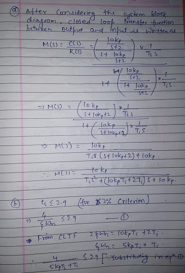
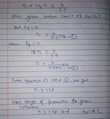
a) The Figure below shows the block diagram of the temperature control system, where Gi(s) is a PI controller transfer function, G2(s) is the fermentation process transfer function 2C320s 1 i) Derive the closed-loop transfer function between R(s) and C(s) ii) Calculate the steady state error when the input R(s) - 37 15] R(s) + C(s) Gi(s) G2(s) b) Consider the fed-batch fermentation process used to produce a thera- peutic protein expressed...
Please help me with part A and B(i)
a) The Figure below shows the block diagram of the temperature control system, where Gi(s) is a PI controller transfer function, G2(s) is the fermentation process transfer function 2C320s 1 i) Derive the closed-loop transfer function between R(s) and C(s) ii) Calculate the steady state error when the input R(s) - 37 15] R(s) + C(s) Gi(s) G2(s) b) Consider the fed-batch fermentation process used to produce a thera- peutic protein expressed...
 please help to solve . Thank you
A4. What is time response of the control system? (around 50 words) (5 marks) A5. A unity feedback system has Open loop Transfer system (s+1). What is its Closed loop Transfer function? (5 marks) A6. A unity feedback system has Open loop Transfer system s/(s+1). What is its Closed loop Transfer function? (5 marks)
please help to solve . Thank you
A4. What is time response of the control system? (around 50 words) (5 marks) A5. A unity feedback system has Open loop Transfer system (s+1). What is its Closed loop Transfer function? (5 marks) A6. A unity feedback system has Open loop Transfer system s/(s+1). What is its Closed loop Transfer function? (5 marks)
 I have no more posting for this month, please solve these for me
thanks
1. Given the following unity feedback system where s+z s2 (s + 10) and the controller is a proportional controller Ge = K, do the following: a. If z = 2, find K so that the damped frequency of the oscillation of the transient response is 5 rad/s. b. The system is to be redesigned by changing the values of z and K. If the new...
I have no more posting for this month, please solve these for me
thanks
1. Given the following unity feedback system where s+z s2 (s + 10) and the controller is a proportional controller Ge = K, do the following: a. If z = 2, find K so that the damped frequency of the oscillation of the transient response is 5 rad/s. b. The system is to be redesigned by changing the values of z and K. If the new...
 Please solve part b and c and d !!
Consider the closed loop system shown in Figure 4. The root locus of that system is shown in Figure 5 (s+40s+8) R(s) Y(s) Figure 4 System block diagram of Problem 4 a) On the root locus plot, sketch the region of possible roots of the dominant closed-loop poles such that the system response to a unit step has the following time domain specifications. [5] i. Damping ratio, 20.76 ii. Natural frequency,....
Please solve part b and c and d !!
Consider the closed loop system shown in Figure 4. The root locus of that system is shown in Figure 5 (s+40s+8) R(s) Y(s) Figure 4 System block diagram of Problem 4 a) On the root locus plot, sketch the region of possible roots of the dominant closed-loop poles such that the system response to a unit step has the following time domain specifications. [5] i. Damping ratio, 20.76 ii. Natural frequency,....
 Please answer any parts that you can do / within
your knowledge! Thank you very much in advance!
As part of its "Think. Difference. Function." student strategy, SNaF2 University wants to add a live in-house band to accompany lectures and play musical interludes. Its President, an award winning media personality, points out that this will "be distinctive," has “co-creation in partnership and that its "collaborative, connected and active" learning will (Also, "jazzing it up" helps justify higher fees. :-) "sound...
Please answer any parts that you can do / within
your knowledge! Thank you very much in advance!
As part of its "Think. Difference. Function." student strategy, SNaF2 University wants to add a live in-house band to accompany lectures and play musical interludes. Its President, an award winning media personality, points out that this will "be distinctive," has “co-creation in partnership and that its "collaborative, connected and active" learning will (Also, "jazzing it up" helps justify higher fees. :-) "sound...
 Consider the closed loop system defined by the following block diagram. a) Compute the transfer function E(s)/R(s). b) Determine the steady state error for a unit-step 1. Controller ant Itly Ro- +- HI- 4단Toy , c) d) e) reference input signal. Determine the steady state error response for a unit-ramp reference input signal. Determine the locations of the closed loop poles of the system. Select system parameters kp and ki in terms of k so that damping coefficient V2/2 and...
 Hello,
I am stuck on this problem as you can see I have tried a lot I
need some help and direction!
Thank you!
A(S)= t it - itat shown in the block diagram and accompanying ind has a forward gain of 105 17. (30pts total) For the next five questions, refer to the feedback system shown in the block di OPAMP schematic. Assume the OPAMP exhibits ideal characteristics and has a forward an 101F + 1012 jio - Vout...
Hello,
I am stuck on this problem as you can see I have tried a lot I
need some help and direction!
Thank you!
A(S)= t it - itat shown in the block diagram and accompanying ind has a forward gain of 105 17. (30pts total) For the next five questions, refer to the feedback system shown in the block di OPAMP schematic. Assume the OPAMP exhibits ideal characteristics and has a forward an 101F + 1012 jio - Vout...
 Control Assignment 2017/18 In order to complete this assignment you will have to consider a system which is unique to you. Th parameters of the system are derived from your student mumber and so if you use the wrong mumber you will get the wrong answers and will lose marks. Use the last two digits of your student mumber where Ki-last but_one_digit+I and K-last digit+1. Thus the mumber 201656789 would give K9 and K 10. When you submit your report,...
 I got A,B,C done can you do D,E,F
Also can you check my solutions please. Thank you ?
Question 1 - Consider an unit feedback system whose open-loop transfer function is G(s)-k/ ((s + 1)(s 2 +4s 25)) A. Draw Bode plot of the open-loop system for k-75 B. Calculate the phase and magnitude of G(s) at 1 rad/s for k 75 C. Determine the cross-over frequency, and the phase and gain margins for k-75 (14 marks D. What is...
I got A,B,C done can you do D,E,F
Also can you check my solutions please. Thank you ?
Question 1 - Consider an unit feedback system whose open-loop transfer function is G(s)-k/ ((s + 1)(s 2 +4s 25)) A. Draw Bode plot of the open-loop system for k-75 B. Calculate the phase and magnitude of G(s) at 1 rad/s for k 75 C. Determine the cross-over frequency, and the phase and gain margins for k-75 (14 marks D. What is...
 Please fill in table below and answer question 2+3.
Thank you very much and I hope you have a great day!
1. A circuit that contains one battery, two switches (labeled S, and S2) and two lamps (labeled Li and L2) is to be designed so that it does the following: 1) If only S is closed, nothing will happen. 2) If only S2 is closed, only L2 will light. 3) If both switches are closed, both lamps will light....
Please fill in table below and answer question 2+3.
Thank you very much and I hope you have a great day!
1. A circuit that contains one battery, two switches (labeled S, and S2) and two lamps (labeled Li and L2) is to be designed so that it does the following: 1) If only S is closed, nothing will happen. 2) If only S2 is closed, only L2 will light. 3) If both switches are closed, both lamps will light....
 Please help me with part A and B(i)
a) The Figure below shows the block diagram of the temperature control system, where Gi(s) is a PI controller transfer function, G2(s) is the fermentation process transfer function 2C320s 1 i) Derive the closed-loop transfer function between R(s) and C(s) ii) Calculate the steady state error when the input R(s) - 37 15] R(s) + C(s) Gi(s) G2(s) b) Consider the fed-batch fermentation process used to produce a thera- peutic protein expressed...
Please help me with part A and B(i)
a) The Figure below shows the block diagram of the temperature control system, where Gi(s) is a PI controller transfer function, G2(s) is the fermentation process transfer function 2C320s 1 i) Derive the closed-loop transfer function between R(s) and C(s) ii) Calculate the steady state error when the input R(s) - 37 15] R(s) + C(s) Gi(s) G2(s) b) Consider the fed-batch fermentation process used to produce a thera- peutic protein expressed...
Most questions answered within 3 hours.
-
Assembly Programming
INCLUDE Irvine32.inc
Make a program that takes a string and a word as inputs...
asked 4 minutes ago -
Can I get a C++ code and output for this program using classes
instead of using...
asked 9 minutes ago -
A 4.0 L flask containing chlorine gas is connected to an
evacuated 3.0 L flask. If...
asked 20 minutes ago -
The number of years of education of self-employed individuals in
the United States has a population...
asked 7 minutes ago -
Write an essay containing your thoughts on
whether corporations should be limited in the amount of...
asked 21 minutes ago -
Given the following two sequences x (n)=[3 , 11,7 ,0 ,−1, 4 ,2
],−3≤n≤ 3 ;...
asked 20 minutes ago -
What is the minimal sample size needed for a 95% confidence
interval to have a maximal...
asked 22 minutes ago -
1. Methods of collecting data - Experiments and direct
observation
In each of the following situations,...
asked 35 minutes ago -
Each protein is composed of a maximum of ____________ different
amino acids in varying numbers and...
asked 52 minutes ago -
One member in the comp set that did not have supply, demand, and
revenue data. What...
asked 30 minutes ago -
What is the density of a substance that takes up 3.4e3 cubic cm
and weighs 1.96...
asked 45 minutes ago -
Consider a single wire loop of radius a. Calculate the magnetic
field B(z) along the axis...
asked 41 minutes ago