1)

help me with this question. solution is posted. please help step by step of how to get the solution.
2)

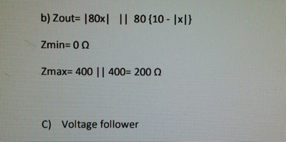
same with the above question also. solution posted. please explain. just part b on the second question. Thanks
Homework Answers
![Resistance of ba, RP: 800 . Resistance of bos 266 Pp R,ון]800-R)+3.RJ pedance, Ło- , d久.](http://img.homeworklib.com/questions/ea8b32b0-bdce-11eb-98e6-1d498d2e631a.png?x-oss-process=image/resize,w_560)


Add Answer to:
1)
help me with this question. solution is posted. please
help step by step of how...
Question 4 (8%) The potentiometer circuit shown in Fig. 3 is used to measure angular position 0. The capacitor C is use...
 Question 4 (8%) The potentiometer circuit shown in Fig. 3 is used to measure angular position 0. The capacitor C is used to reduce contact bounce, and the op-amp isolates the potentiometer from long lead wires and recording instrument resistance loading. The potentiometer being used rotate 320 degrees has a resistance Rp 4.0k2, and is capable of dissipating 0.02W of power in most environments. The circuit is to have a minimum sensitivity of 10.0mV/degree when 100m of AWG28 copper lead...
Please answer me step by step thanks Question 2: Th is question relates to diodes and...
 Please answer me step by step thanks
Question 2: Th is question relates to diodes and transistor amplifiers The following question relates to the diode circuit in Figure 2a below. if t E- SV, and the diode was a Red LED, determine; (i) the voltage across the diode, Vo (ii) the value of resistor R, that will give a current, 1 4mA (ii) the current, I, if E--5V (a) he voltage source Figure 2a 8 marks] er amplifier circuit shown...
Please answer me step by step thanks
Question 2: Th is question relates to diodes and transistor amplifiers The following question relates to the diode circuit in Figure 2a below. if t E- SV, and the diode was a Red LED, determine; (i) the voltage across the diode, Vo (ii) the value of resistor R, that will give a current, 1 4mA (ii) the current, I, if E--5V (a) he voltage source Figure 2a 8 marks] er amplifier circuit shown...
I need help with these question. please show step by step solution. make sure the answer...
 I need help with these question. please show step by step
solution. make sure the answer is correct.
Question 1 (1 point) In a double-slit experiment it is found that light of a wavelength 512 nm gives a second-order maximum at a certain location on the screen. What wavelength of light would have a minimum at the same location? Your Answer: Answer units Question 2 (1 point) A thin oil slick (n=2.0) floats on water (n=1.33). A beam of white...
I need help with these question. please show step by step
solution. make sure the answer is correct.
Question 1 (1 point) In a double-slit experiment it is found that light of a wavelength 512 nm gives a second-order maximum at a certain location on the screen. What wavelength of light would have a minimum at the same location? Your Answer: Answer units Question 2 (1 point) A thin oil slick (n=2.0) floats on water (n=1.33). A beam of white...
I need help with these question. please show step by step solution to get to correct...
 I need help with these question. please show step by step
solution to get to correct answer. Correct answer is shown in
blue.
Question 2 0/1 point Athin oil slick (n-2.0) floats on water (n=1.33). A beam of white light strikes the oil at normal incidence from air. The only enhanced reflected wavelengths are 240 nm and 400 nm. What is the minimum thickness of the oil slick? Answer: 150 % (48) nm Question 3 0/1 point Three polarizers are...
I need help with these question. please show step by step
solution to get to correct answer. Correct answer is shown in
blue.
Question 2 0/1 point Athin oil slick (n-2.0) floats on water (n=1.33). A beam of white light strikes the oil at normal incidence from air. The only enhanced reflected wavelengths are 240 nm and 400 nm. What is the minimum thickness of the oil slick? Answer: 150 % (48) nm Question 3 0/1 point Three polarizers are...
Please help me find the solution in a step by step. Thank you. I have updated...
 Please help me find the solution in a step by step. Thank
you.
I have updated the picture please let me know if it can still be
seen.thank you
Question: The following data were obtained for 1.00 cm samples of a particular chemical. What is the concentration of a 1.00 cm sample that has an absorbance of 0.60? Conc. Abs. 0.50 0.69 0.40 0.55 0.30 0.41 0.20 0.27 2. 3 Concentration (M)
Please help me find the solution in a step by step. Thank
you.
I have updated the picture please let me know if it can still be
seen.thank you
Question: The following data were obtained for 1.00 cm samples of a particular chemical. What is the concentration of a 1.00 cm sample that has an absorbance of 0.60? Conc. Abs. 0.50 0.69 0.40 0.55 0.30 0.41 0.20 0.27 2. 3 Concentration (M)
Please help me to solve it... And what is the weird symbol used in the solution??...
 Please help me to solve it... And what is the weird
symbol used in the solution??
L- dI + Ri et dt konditoriohm) Lo Series with R = thyernton (ohm) L Inductor (Henrys) E source of electro motive force that supplies a voltage (volt) t = time. 1 = curent (ampere) Following 25. a resistor-indu Cher (RL) series surir, circuit. R-6 ohm 9 L = 6henrys. e(t) = 12 volts. switch off t=0, I = 0 Ampere Find I(t) if...
Please help me to solve it... And what is the weird
symbol used in the solution??
L- dI + Ri et dt konditoriohm) Lo Series with R = thyernton (ohm) L Inductor (Henrys) E source of electro motive force that supplies a voltage (volt) t = time. 1 = curent (ampere) Following 25. a resistor-indu Cher (RL) series surir, circuit. R-6 ohm 9 L = 6henrys. e(t) = 12 volts. switch off t=0, I = 0 Ampere Find I(t) if...
Please help me out with question 18. Its a question of laplace transfromation for unit step...
 Please help me out with question 18.
Its a question of laplace transfromation for unit step
functions .
thanks
lems. Sketch a graph 14. F(s) = e-s (3) +e-> (5) Use Laplace transforms to solve the following initial value problems. Sketo the solution, together with a graph of the driving function. 15. x' + 2x = 2u(t - 3), x(0) = 1 16. x' + x = 2 + ut - 1)e-!, x(0) = 0 17. x" + 4x' +...
Please help me out with question 18.
Its a question of laplace transfromation for unit step
functions .
thanks
lems. Sketch a graph 14. F(s) = e-s (3) +e-> (5) Use Laplace transforms to solve the following initial value problems. Sketo the solution, together with a graph of the driving function. 15. x' + 2x = 2u(t - 3), x(0) = 1 16. x' + x = 2 + ut - 1)e-!, x(0) = 0 17. x" + 4x' +...
I have posted this question 4 times previous with 4 different answers. note, there is a step in o...
 I have posted this question 4 times previous with 4 different
answers. note, there is a step in output voltage when D1 changes to
forward bias.
Please do not answer this question unless you know the correct
answer.
Question 2 For the circuit shown in Figure 2, determine its sketch transfer characteristics. Diodes have Voo 0 V and R 50 50Ω D1 100 Ω 1500 V 2.5V Figure 2. Please answer clearly
Question 2 For the circuit shown in Figure...
I have posted this question 4 times previous with 4 different
answers. note, there is a step in output voltage when D1 changes to
forward bias.
Please do not answer this question unless you know the correct
answer.
Question 2 For the circuit shown in Figure 2, determine its sketch transfer characteristics. Diodes have Voo 0 V and R 50 50Ω D1 100 Ω 1500 V 2.5V Figure 2. Please answer clearly
Question 2 For the circuit shown in Figure...
please help Question 1 Consider the following circuit, where the reverse saturation current (Is) is the...
 please help
Question 1 Consider the following circuit, where the reverse saturation current (Is) is the same for each diode. D2 o Vo Di Vi WWW R 32 23 a. b. Determine an algebraic expression for V1, for a given Vo, and Is. Given an Is of 40 FA and R1 = 3.3 kl , determine the Vi that produces an output voltage (V.) of 0.625 V. C. Recalculate question-b if Is were to be a thousand times greater at...
please help
Question 1 Consider the following circuit, where the reverse saturation current (Is) is the same for each diode. D2 o Vo Di Vi WWW R 32 23 a. b. Determine an algebraic expression for V1, for a given Vo, and Is. Given an Is of 40 FA and R1 = 3.3 kl , determine the Vi that produces an output voltage (V.) of 0.625 V. C. Recalculate question-b if Is were to be a thousand times greater at...
Could you please show me how I can drw those circuits. please using (NI Multisim 14)...
 Could you please show me how I can drw those circuits.
please using (NI Multisim 14)
Optocoupler Objectives Use an ohmmeter to determine the condition of the optoisolator. Observe the operation of an optocoupler. Determine the maximum frequency response of the optocoupler. Required Materials (1) Dual DC power supply (1) Function generator (1) Oscilloscope (2) Multimeters (1) Optocoupler (ECG3040) (1) 3.9ΚΩ resistor (1) 220 resistor Introduction An optoisolator is a hybrid integrated circuit that contains an LED on one side...
Could you please show me how I can drw those circuits.
please using (NI Multisim 14)
Optocoupler Objectives Use an ohmmeter to determine the condition of the optoisolator. Observe the operation of an optocoupler. Determine the maximum frequency response of the optocoupler. Required Materials (1) Dual DC power supply (1) Function generator (1) Oscilloscope (2) Multimeters (1) Optocoupler (ECG3040) (1) 3.9ΚΩ resistor (1) 220 resistor Introduction An optoisolator is a hybrid integrated circuit that contains an LED on one side...
 Question 4 (8%) The potentiometer circuit shown in Fig. 3 is used to measure angular position 0. The capacitor C is used to reduce contact bounce, and the op-amp isolates the potentiometer from long lead wires and recording instrument resistance loading. The potentiometer being used rotate 320 degrees has a resistance Rp 4.0k2, and is capable of dissipating 0.02W of power in most environments. The circuit is to have a minimum sensitivity of 10.0mV/degree when 100m of AWG28 copper lead...
 Please answer me step by step thanks
Question 2: Th is question relates to diodes and transistor amplifiers The following question relates to the diode circuit in Figure 2a below. if t E- SV, and the diode was a Red LED, determine; (i) the voltage across the diode, Vo (ii) the value of resistor R, that will give a current, 1 4mA (ii) the current, I, if E--5V (a) he voltage source Figure 2a 8 marks] er amplifier circuit shown...
Please answer me step by step thanks
Question 2: Th is question relates to diodes and transistor amplifiers The following question relates to the diode circuit in Figure 2a below. if t E- SV, and the diode was a Red LED, determine; (i) the voltage across the diode, Vo (ii) the value of resistor R, that will give a current, 1 4mA (ii) the current, I, if E--5V (a) he voltage source Figure 2a 8 marks] er amplifier circuit shown...
 I need help with these question. please show step by step
solution. make sure the answer is correct.
Question 1 (1 point) In a double-slit experiment it is found that light of a wavelength 512 nm gives a second-order maximum at a certain location on the screen. What wavelength of light would have a minimum at the same location? Your Answer: Answer units Question 2 (1 point) A thin oil slick (n=2.0) floats on water (n=1.33). A beam of white...
I need help with these question. please show step by step
solution. make sure the answer is correct.
Question 1 (1 point) In a double-slit experiment it is found that light of a wavelength 512 nm gives a second-order maximum at a certain location on the screen. What wavelength of light would have a minimum at the same location? Your Answer: Answer units Question 2 (1 point) A thin oil slick (n=2.0) floats on water (n=1.33). A beam of white...
 I need help with these question. please show step by step
solution to get to correct answer. Correct answer is shown in
blue.
Question 2 0/1 point Athin oil slick (n-2.0) floats on water (n=1.33). A beam of white light strikes the oil at normal incidence from air. The only enhanced reflected wavelengths are 240 nm and 400 nm. What is the minimum thickness of the oil slick? Answer: 150 % (48) nm Question 3 0/1 point Three polarizers are...
I need help with these question. please show step by step
solution to get to correct answer. Correct answer is shown in
blue.
Question 2 0/1 point Athin oil slick (n-2.0) floats on water (n=1.33). A beam of white light strikes the oil at normal incidence from air. The only enhanced reflected wavelengths are 240 nm and 400 nm. What is the minimum thickness of the oil slick? Answer: 150 % (48) nm Question 3 0/1 point Three polarizers are...
 Please help me find the solution in a step by step. Thank
you.
I have updated the picture please let me know if it can still be
seen.thank you
Question: The following data were obtained for 1.00 cm samples of a particular chemical. What is the concentration of a 1.00 cm sample that has an absorbance of 0.60? Conc. Abs. 0.50 0.69 0.40 0.55 0.30 0.41 0.20 0.27 2. 3 Concentration (M)
Please help me find the solution in a step by step. Thank
you.
I have updated the picture please let me know if it can still be
seen.thank you
Question: The following data were obtained for 1.00 cm samples of a particular chemical. What is the concentration of a 1.00 cm sample that has an absorbance of 0.60? Conc. Abs. 0.50 0.69 0.40 0.55 0.30 0.41 0.20 0.27 2. 3 Concentration (M)
 Please help me to solve it... And what is the weird
symbol used in the solution??
L- dI + Ri et dt konditoriohm) Lo Series with R = thyernton (ohm) L Inductor (Henrys) E source of electro motive force that supplies a voltage (volt) t = time. 1 = curent (ampere) Following 25. a resistor-indu Cher (RL) series surir, circuit. R-6 ohm 9 L = 6henrys. e(t) = 12 volts. switch off t=0, I = 0 Ampere Find I(t) if...
Please help me to solve it... And what is the weird
symbol used in the solution??
L- dI + Ri et dt konditoriohm) Lo Series with R = thyernton (ohm) L Inductor (Henrys) E source of electro motive force that supplies a voltage (volt) t = time. 1 = curent (ampere) Following 25. a resistor-indu Cher (RL) series surir, circuit. R-6 ohm 9 L = 6henrys. e(t) = 12 volts. switch off t=0, I = 0 Ampere Find I(t) if...
 Please help me out with question 18.
Its a question of laplace transfromation for unit step
functions .
thanks
lems. Sketch a graph 14. F(s) = e-s (3) +e-> (5) Use Laplace transforms to solve the following initial value problems. Sketo the solution, together with a graph of the driving function. 15. x' + 2x = 2u(t - 3), x(0) = 1 16. x' + x = 2 + ut - 1)e-!, x(0) = 0 17. x" + 4x' +...
Please help me out with question 18.
Its a question of laplace transfromation for unit step
functions .
thanks
lems. Sketch a graph 14. F(s) = e-s (3) +e-> (5) Use Laplace transforms to solve the following initial value problems. Sketo the solution, together with a graph of the driving function. 15. x' + 2x = 2u(t - 3), x(0) = 1 16. x' + x = 2 + ut - 1)e-!, x(0) = 0 17. x" + 4x' +...
 I have posted this question 4 times previous with 4 different
answers. note, there is a step in output voltage when D1 changes to
forward bias.
Please do not answer this question unless you know the correct
answer.
Question 2 For the circuit shown in Figure 2, determine its sketch transfer characteristics. Diodes have Voo 0 V and R 50 50Ω D1 100 Ω 1500 V 2.5V Figure 2. Please answer clearly
Question 2 For the circuit shown in Figure...
I have posted this question 4 times previous with 4 different
answers. note, there is a step in output voltage when D1 changes to
forward bias.
Please do not answer this question unless you know the correct
answer.
Question 2 For the circuit shown in Figure 2, determine its sketch transfer characteristics. Diodes have Voo 0 V and R 50 50Ω D1 100 Ω 1500 V 2.5V Figure 2. Please answer clearly
Question 2 For the circuit shown in Figure...
 please help
Question 1 Consider the following circuit, where the reverse saturation current (Is) is the same for each diode. D2 o Vo Di Vi WWW R 32 23 a. b. Determine an algebraic expression for V1, for a given Vo, and Is. Given an Is of 40 FA and R1 = 3.3 kl , determine the Vi that produces an output voltage (V.) of 0.625 V. C. Recalculate question-b if Is were to be a thousand times greater at...
please help
Question 1 Consider the following circuit, where the reverse saturation current (Is) is the same for each diode. D2 o Vo Di Vi WWW R 32 23 a. b. Determine an algebraic expression for V1, for a given Vo, and Is. Given an Is of 40 FA and R1 = 3.3 kl , determine the Vi that produces an output voltage (V.) of 0.625 V. C. Recalculate question-b if Is were to be a thousand times greater at...
 Could you please show me how I can drw those circuits.
please using (NI Multisim 14)
Optocoupler Objectives Use an ohmmeter to determine the condition of the optoisolator. Observe the operation of an optocoupler. Determine the maximum frequency response of the optocoupler. Required Materials (1) Dual DC power supply (1) Function generator (1) Oscilloscope (2) Multimeters (1) Optocoupler (ECG3040) (1) 3.9ΚΩ resistor (1) 220 resistor Introduction An optoisolator is a hybrid integrated circuit that contains an LED on one side...
Could you please show me how I can drw those circuits.
please using (NI Multisim 14)
Optocoupler Objectives Use an ohmmeter to determine the condition of the optoisolator. Observe the operation of an optocoupler. Determine the maximum frequency response of the optocoupler. Required Materials (1) Dual DC power supply (1) Function generator (1) Oscilloscope (2) Multimeters (1) Optocoupler (ECG3040) (1) 3.9ΚΩ resistor (1) 220 resistor Introduction An optoisolator is a hybrid integrated circuit that contains an LED on one side...
Most questions answered within 3 hours.
-
2. Use the following information in the table to answer the
following questions. (Numbers are in...
asked 2 minutes from now -
The rate constant of a first-order reaction is 2.95 × 10⁻⁴ s−1
at 350.° C. If...
asked 27 seconds ago -
The fuel economy of a 2011 Lexus RX 350 2wd 6 cylinder 3.5 L
automatic 5...
asked 5 minutes ago -
i.
the synthesized compund 2-bromo-butanal i have a IR peak at about
3200 and one at...
asked 5 minutes ago -
A
752 mL sample of water was placed in a 1000 gram pan of aluminum.
The...
asked 16 minutes ago -
1.In the context of chelation, what does binding strength mean?
What happens at the molecular level...
asked 9 minutes ago -
Describe two obstacles that makes fixing atmospheric nitrogen
difficult.
asked 29 minutes ago -
Evelyn incorporates her sole proprietorship, transferring it to
newly formed Papaya Corporation. The assets transferred have...
asked 15 minutes ago -
Assume that in a hydrogen atom, the electron circles the nucleus
in a circle of radius...
asked 24 minutes ago -
1 point) Given the significance level α=0.01 find the following:
(a) left-tailed z value z= (b)...
asked 18 minutes ago -
Calculate the expected value, the variance, and the standard
deviation of the given random variable X....
asked 19 minutes ago -
T
F 53) Most differences
between human groups are the result of biology rather than
culture....
asked 33 minutes ago