
Homework Answers


Add Answer to:
- 0 L-100mH For the circuit shown, if the initial current in the inductor was zero,...
2.5 QUESTION 8 Find the inductor current in the circuit shown below. Given L = 100...
 2.5 QUESTION 8 Find the inductor current in the circuit shown below. Given L = 100 mH, V = 200cos 80t V, and i(0) =0 A IL vL(C) [2.5 sin 80t] A (-2.5 cos 80t] A -2.5 sin 80t] A t2.5 cos 80t] A
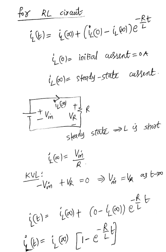
As shown in the figure, a simple RL circuit (L = 1H) is powered by a...
 As shown in the figure, a simple RL circuit (L = 1H) is powered by a 10 V batterey. The initial current in the circuit is zero. (el-0.367 -0.135, -0.049, e---0.018, e'-0.006) R t-0)0 time (sec) Vc (Volt) MW 6.33 8.65 9.51 9.82 9.94 3 4 5 6 7 8 sec.) a) Calculate the time constant of the RL circuit using the graph given above. O b) Calculate VR(t) the voltage across the resistor R. as a function of time....
An RL circuit is fabricated as shown with an unknown resistor and real inductor. They are...
 An RL circuit is fabricated as shown with an unknown resistor and real inductor. They are connected to a 12.0 V frequency generator that is set to 170. Hz. Two voltages are measured, VCA = 8.69 V and VBC = 6.59 V. What is the time constant of this circuit. (HINT: Use the phasor diagram shown to determine expressions for the phase constant, inductance and internal resistance of the inductor. Current is not shown since it is a series circuit.)...
Please determine the following: a) The initial inductor current i(0−) b) The final inductor current i_final...
 Please determine the following:
a) The initial inductor current i(0−)
b) The final inductor current i_final long after the switches
have changed.
c) A neat circuit schematic for the transient period.
d) A differential equation for the inductor current in the
circuit shown in part c.
e) The solution of the differential equation for t ≥ 0
3. You are given the circuit shown below. The switch was open for a long time before t = 0. lit) 5 H...
Please determine the following:
a) The initial inductor current i(0−)
b) The final inductor current i_final long after the switches
have changed.
c) A neat circuit schematic for the transient period.
d) A differential equation for the inductor current in the
circuit shown in part c.
e) The solution of the differential equation for t ≥ 0
3. You are given the circuit shown below. The switch was open for a long time before t = 0. lit) 5 H...
Assume that the inductor in this circuit is an ideal (lossless) device, initial current is 0A....
 Assume that the inductor in this circuit is an ideal
(lossless) device, initial current is 0A. At t=0, turn on the
switch; at t= 5t, turn off the switch. a-f please
2. Assume that the inductor in this circuit is an ideal (lossless) device, initial current is OA. At t-o, turn on the switch; at t. 5 τ, turn off the switch. (50pts) For 0 s t s5r: switch on a) Find the Thevenin equivalent circuit for the circuit inside...
Assume that the inductor in this circuit is an ideal
(lossless) device, initial current is 0A. At t=0, turn on the
switch; at t= 5t, turn off the switch. a-f please
2. Assume that the inductor in this circuit is an ideal (lossless) device, initial current is OA. At t-o, turn on the switch; at t. 5 τ, turn off the switch. (50pts) For 0 s t s5r: switch on a) Find the Thevenin equivalent circuit for the circuit inside...
ON CAPAC Transient RL Circuit Consider the circuit shown in the figure. The resistance of the...
 ON CAPAC Transient RL Circuit Consider the circuit shown in the figure. The resistance of the wire used to make the inductor is negligible compared to the resistors in the circuit. V-140 V, R; -10.Ohms, Ry - 1100 Ohms, and L-200 H RI WWW For this part, assume that switch S has been closed for a long time so that steady currents exist in the circuit. Find (1) the battery current, (2) the current in resistor Ry, and (3) the...
A circuit is constructed with two capacitors and an inductor as shown. The values for the...
 A circuit is constructed with two capacitors and an inductor as shown. The values for the capacitors are: C1 = 426 uF and C2 = 232 pF. The inductance is L = 257 mH. At time t =0, the current through the inductor has its maximum value IL(0) = 139 mA and it has the direction shown. La "What is wo, the resonant frequency of this circuit? 160.95 radians/s Submit 21 What is Q1(t1), the charge on the capacitor C1...
3. Natural response, for ? > 0 of a series R-L-C circuit has R = 1...
3. Natural response, for ? > 0 of a series R-L-C circuit has R = 1 Ω , L = 1 H and C = 1 F. The initial capacitor voltage is 4 V, and initial inductor current is zero. The series current is i. (i) Draw the time domain circuit. (ii) Draw the Laplace transform domain circuit. (iii) From (ii), determine Io =Io (s) (iv) From (iii), determine ?? = ??(?) for t > 0
4. Obtain equations for the inductor voltage vL(t) and the inductor current iL(t) for the circuit...
 4. Obtain equations for the inductor voltage vL(t) and the inductor current iL(t) for the circuit in Figure 4. Based on the equations, determine the final value of the inductor current and the initial value of the inductor voltage. Furthermore, utilize the voltage and current equations to obtain the values for vr(7) and iL(T). What fraction of its final value is iL(T)? What fraction of its initial value is vL(T)? 1 2 L1 2.2mH R1 V1 1kQ OV 5V swn1.54e-5s...
Problem 5 (20 Points): For the circuit shown below, the input is the current source, I(t) and the...
 Problem 5 (20 Points): For the circuit shown below, the input is the current source, I(t) and the output is eo. 1). Find the state variable model. Take ec and IL as state variables (refer notes from Chapter-6). 2). Apply Laplace Transform on the state variable model (from part-1) and show that the transform of the output (eo) is given by the expression: 사스 ; if the initial conditions, L(0) and ec(0) are known. Note: ec(0)-eo(0) R L R L...
 2.5 QUESTION 8 Find the inductor current in the circuit shown below. Given L = 100 mH, V = 200cos 80t V, and i(0) =0 A IL vL(C) [2.5 sin 80t] A (-2.5 cos 80t] A -2.5 sin 80t] A t2.5 cos 80t] A
 As shown in the figure, a simple RL circuit (L = 1H) is powered by a 10 V batterey. The initial current in the circuit is zero. (el-0.367 -0.135, -0.049, e---0.018, e'-0.006) R t-0)0 time (sec) Vc (Volt) MW 6.33 8.65 9.51 9.82 9.94 3 4 5 6 7 8 sec.) a) Calculate the time constant of the RL circuit using the graph given above. O b) Calculate VR(t) the voltage across the resistor R. as a function of time....
 An RL circuit is fabricated as shown with an unknown resistor and real inductor. They are connected to a 12.0 V frequency generator that is set to 170. Hz. Two voltages are measured, VCA = 8.69 V and VBC = 6.59 V. What is the time constant of this circuit. (HINT: Use the phasor diagram shown to determine expressions for the phase constant, inductance and internal resistance of the inductor. Current is not shown since it is a series circuit.)...
 Please determine the following:
a) The initial inductor current i(0−)
b) The final inductor current i_final long after the switches
have changed.
c) A neat circuit schematic for the transient period.
d) A differential equation for the inductor current in the
circuit shown in part c.
e) The solution of the differential equation for t ≥ 0
3. You are given the circuit shown below. The switch was open for a long time before t = 0. lit) 5 H...
Please determine the following:
a) The initial inductor current i(0−)
b) The final inductor current i_final long after the switches
have changed.
c) A neat circuit schematic for the transient period.
d) A differential equation for the inductor current in the
circuit shown in part c.
e) The solution of the differential equation for t ≥ 0
3. You are given the circuit shown below. The switch was open for a long time before t = 0. lit) 5 H...
 Assume that the inductor in this circuit is an ideal
(lossless) device, initial current is 0A. At t=0, turn on the
switch; at t= 5t, turn off the switch. a-f please
2. Assume that the inductor in this circuit is an ideal (lossless) device, initial current is OA. At t-o, turn on the switch; at t. 5 τ, turn off the switch. (50pts) For 0 s t s5r: switch on a) Find the Thevenin equivalent circuit for the circuit inside...
Assume that the inductor in this circuit is an ideal
(lossless) device, initial current is 0A. At t=0, turn on the
switch; at t= 5t, turn off the switch. a-f please
2. Assume that the inductor in this circuit is an ideal (lossless) device, initial current is OA. At t-o, turn on the switch; at t. 5 τ, turn off the switch. (50pts) For 0 s t s5r: switch on a) Find the Thevenin equivalent circuit for the circuit inside...
 ON CAPAC Transient RL Circuit Consider the circuit shown in the figure. The resistance of the wire used to make the inductor is negligible compared to the resistors in the circuit. V-140 V, R; -10.Ohms, Ry - 1100 Ohms, and L-200 H RI WWW For this part, assume that switch S has been closed for a long time so that steady currents exist in the circuit. Find (1) the battery current, (2) the current in resistor Ry, and (3) the...
 A circuit is constructed with two capacitors and an inductor as shown. The values for the capacitors are: C1 = 426 uF and C2 = 232 pF. The inductance is L = 257 mH. At time t =0, the current through the inductor has its maximum value IL(0) = 139 mA and it has the direction shown. La "What is wo, the resonant frequency of this circuit? 160.95 radians/s Submit 21 What is Q1(t1), the charge on the capacitor C1...
 4. Obtain equations for the inductor voltage vL(t) and the inductor current iL(t) for the circuit in Figure 4. Based on the equations, determine the final value of the inductor current and the initial value of the inductor voltage. Furthermore, utilize the voltage and current equations to obtain the values for vr(7) and iL(T). What fraction of its final value is iL(T)? What fraction of its initial value is vL(T)? 1 2 L1 2.2mH R1 V1 1kQ OV 5V swn1.54e-5s...
 Problem 5 (20 Points): For the circuit shown below, the input is the current source, I(t) and the output is eo. 1). Find the state variable model. Take ec and IL as state variables (refer notes from Chapter-6). 2). Apply Laplace Transform on the state variable model (from part-1) and show that the transform of the output (eo) is given by the expression: 사스 ; if the initial conditions, L(0) and ec(0) are known. Note: ec(0)-eo(0) R L R L...
Most questions answered within 3 hours.
-
If the carrying amount is $200,000 and recoverable amount is
$205000, the impairment amount is:
Select...
asked 1 minute ago -
The correlation is inappropriate as a measure of association
between two quantitative variables (you may select...
asked 6 minutes ago -
USE THE DATA IN THE TABLE BELOW TO ANSWER QUESTIONS 19 – 24
(Assume all account...
asked 8 minutes ago -
In a population of interest, we know that, 77% drink coffee, and
23% drink tea. Assume...
asked 9 minutes ago -
Mahaley, Inc., manufactures and sells two products: Product Q9
and Product F0. Data concerning the expected...
asked 23 minutes ago -
To measure the current through one branch of a parallel circuit,
the meter is connected ________....
asked 27 minutes ago -
a)
The following table shows the profile, by the math section of
the SAT Reasoning Test,...
asked 43 minutes ago -
A single loop of aluminum wire, lying flat in a plane, has an
area of 7.80...
asked 34 minutes ago -
A fair die is rolled. What is the probability of the dice coming
up a one...
asked 38 minutes ago -
A car drives over the crest of a hill of radius 120m with a
speed of...
asked 58 minutes ago -
Implementation of a MapReduce-style distributed word count
application
For this assignment, you can use any programming...
asked 1 hour ago -
In females, the labia swells and the vagin-a lubricates during
which phase of the sexual response...
asked 1 hour ago