

Homework Answers


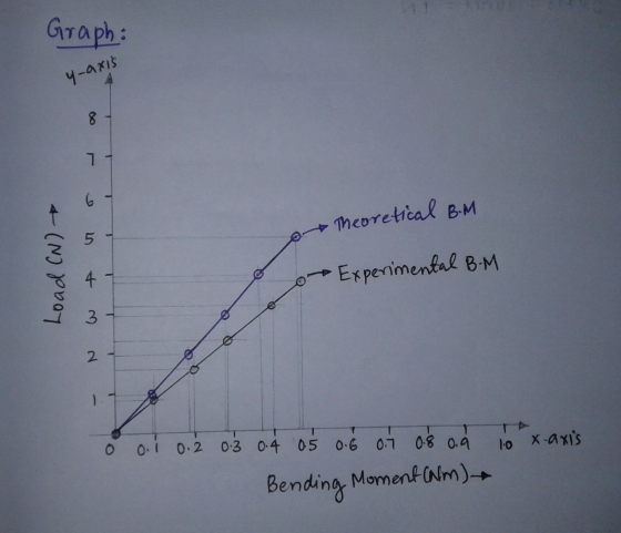

Experimental and Theoretical Bending moments are calculated for the load.
Graph of B.M Vs Load is drawn for experimental and theoretical values.
Graph is a linear straight line .
The formula used to find B.M accurately predict the behaviour of the beam (only slight variations ).
(Please give a thumbs up ).
Add Answer to:
Experiment 1: Bending Moment Variation at the point of Loading This experiment examines how bending moment...
The meter is only ±0.1N, lightly tap the frame (there may be a little 'stiction') Experiment 1: S...
 Draw shear diagram for the first two loads.
the meter is only ±0.1N, lightly tap the frame (there may be a little 'stiction') Experiment 1: Shear Force Variation with an Increasing Point Load This experiment examines how shear force varies with an increasing point load. Figure 3 shows the force diagram for the beam. Draw the shear diagram for the first load case (W 0.98 N) 40 mm Cut V (N) o Figure 3 Force Diagram aton we will use...
Draw shear diagram for the first two loads.
the meter is only ±0.1N, lightly tap the frame (there may be a little 'stiction') Experiment 1: Shear Force Variation with an Increasing Point Load This experiment examines how shear force varies with an increasing point load. Figure 3 shows the force diagram for the beam. Draw the shear diagram for the first load case (W 0.98 N) 40 mm Cut V (N) o Figure 3 Force Diagram aton we will use...
Question 2: A simply supported beam under loading as shown in Figure 1: 1. Draw the influence lines of the bending moment and shear force at point C (L/4) Using the influence lines to determine t...
 Question 2: A simply supported beam under loading as shown in Figure 1: 1. Draw the influence lines of the bending moment and shear force at point C (L/4) Using the influence lines to determine the bending moment and shear force at section C due to the loading as shown in the figure. 2. 3. There is a distributed live load (w#2.5kN/m) which can vary the location along the beam. Determine the location of the live loads which create the...
By deatiles please! Q1. The figure shown below is extracted from bending stress in a beam experiment where an inverted Aluminum (E 69 GPa) T-section is subjected to two point-Loads (each 1/2W). The...
 By deatiles please!
Q1. The figure shown below is extracted from bending stress in a beam experiment where an inverted Aluminum (E 69 GPa) T-section is subjected to two point-Loads (each 1/2W). The strain across the depth of the cross section is measured using strain gauges which are sensors that experience a change in electrical resistance when stretched or compressed. Connections to digital strain display Beam Loading frame Pin support -Retaining pin Strain gauges Locating hole for STRBA load cel...
By deatiles please!
Q1. The figure shown below is extracted from bending stress in a beam experiment where an inverted Aluminum (E 69 GPa) T-section is subjected to two point-Loads (each 1/2W). The strain across the depth of the cross section is measured using strain gauges which are sensors that experience a change in electrical resistance when stretched or compressed. Connections to digital strain display Beam Loading frame Pin support -Retaining pin Strain gauges Locating hole for STRBA load cel...
Assume a beam has the loading shown and a rectangular cross section. is at the center...
 Assume a beam has the loading shown and a rectangular cross section. is at the center and G is at the bottom. Assume point E is at the top, F Cross Sectional View of plane cut at B 400 lb 4 in 500 lb 3 in 10 in. 15 it 1 5 in 1) The beam is cut along a face at B that is perpendicular to the X axis. What is the internal resistive shear force at this face?...
For the simply supported beam subjected to the loading shown, derive equations for the shear force V and the bending moment M for any location in the beam. (Place the origin at point A.) Let w = 7.0 kips/ft, a= 9.0 ft, and b= 20.5 ft. Construct the shear
 For the simply supported beam subjected to the loading shown, derive equations for the shear force V and the bending moment M for any location in the beam. (Place the origin at point A.) Let w = 7.0 kips/ft, a= 9.0 ft, and b= 20.5 ft. Construct the shear-force and bending-moment diagrams on paper and use the results to answer the questions.Calculate the reaction forces By and Cy acting on the beam. Positive values for the reactions are indicated by...
Wood Deck Plan: Part Π-Shear & Bending Moment Diagrams Wood Deck Framing Plan-Dimensions & Loading Uniformly...
 Wood Deck Plan: Part Π-Shear & Bending Moment Diagrams Wood Deck Framing Plan-Dimensions & Loading Uniformly Distributed Load STUDENTI "A" No. (feet) (feet) (feet) (feet)(inches) Dead Load (#/ft*) Live Load (#/ft2) 30 10 15 15 15 15 18 18 18 18 18 12 14 16 12 14 16 12 14 16 12 16 12 16 12 16 12 16 12 16 12 10 10 10 12 12 12 12 30 5 40 40 50 50 30 30 40 40 5...
Wood Deck Plan: Part Π-Shear & Bending Moment Diagrams Wood Deck Framing Plan-Dimensions & Loading Unifo...
 Wood Deck Plan: Part Π-Shear & Bending Moment Diagrams Wood Deck Framing Plan-Dimensions & Loading Uniformly Distributed Load STUDENTI "A" No. (feet) (feet) (feet) (feet)(inches) Dead Load (#/ft*) Live Load (#/ft2) 30 10 15 15 15 15 18 18 18 18 18 12 14 16 12 14 16 12 14 16 12 16 12 16 12 16 12 16 12 16 12 10 10 10 12 12 12 12 30 5 40 40 50 50 30 30 40 40 5...
Part C also ask for the internal bending moment at point D Consider the beam shown...
 Part C also ask for the internal bending moment at point D
Consider the beam shown in (Figure 1). Take w = 240 N/m. Follow the sign convention. Determine the internal normal force at point D. Express your answer to three significant figures and include the appropriate units. VI HÅR O ? Np = Value Units Submit Request Answer Figure < 1 of 1 > Part B Determine the internal shear force at point D Express your answer to three...
Part C also ask for the internal bending moment at point D
Consider the beam shown in (Figure 1). Take w = 240 N/m. Follow the sign convention. Determine the internal normal force at point D. Express your answer to three significant figures and include the appropriate units. VI HÅR O ? Np = Value Units Submit Request Answer Figure < 1 of 1 > Part B Determine the internal shear force at point D Express your answer to three...
Problem 3: One way solid slab (10 pts) The slab shown in Figure 2 is 200...
 Problem 3: One way solid slab (10 pts) The slab shown in Figure 2 is 200 mm thick. All beams/girders have 400 x 600 mm sections. All columns have 400 x 400 mm sections. Superimposed dead load = 3 kN/m, live load = 4 kN/mº. No walls used. a) Check the slab thickness for deflection control. b) Determine the ultimate uniform load on a l-m wide typical slab strip. c) Determine the ultimate uniform load transferred to beam 2. d)...
The beam shown (Figure 1) is supported by a pin at A and a cable at...
 The beam shown (Figure 1) is
supported by a pin at A and a cable at B. Two
loads P = 13 kN are applied straight down from the
centerline of the bottom face. Determine the state of stress at the
point shown (Figure 2) in a section 2 m from the wall. The
dimensions are w = 5.2 cm , h = 10.5 cm ,
L = 0.8 m , a = 1.5 cm , and b = 4...
The beam shown (Figure 1) is
supported by a pin at A and a cable at B. Two
loads P = 13 kN are applied straight down from the
centerline of the bottom face. Determine the state of stress at the
point shown (Figure 2) in a section 2 m from the wall. The
dimensions are w = 5.2 cm , h = 10.5 cm ,
L = 0.8 m , a = 1.5 cm , and b = 4...
 Draw shear diagram for the first two loads.
the meter is only ±0.1N, lightly tap the frame (there may be a little 'stiction') Experiment 1: Shear Force Variation with an Increasing Point Load This experiment examines how shear force varies with an increasing point load. Figure 3 shows the force diagram for the beam. Draw the shear diagram for the first load case (W 0.98 N) 40 mm Cut V (N) o Figure 3 Force Diagram aton we will use...
Draw shear diagram for the first two loads.
the meter is only ±0.1N, lightly tap the frame (there may be a little 'stiction') Experiment 1: Shear Force Variation with an Increasing Point Load This experiment examines how shear force varies with an increasing point load. Figure 3 shows the force diagram for the beam. Draw the shear diagram for the first load case (W 0.98 N) 40 mm Cut V (N) o Figure 3 Force Diagram aton we will use...
 Question 2: A simply supported beam under loading as shown in Figure 1: 1. Draw the influence lines of the bending moment and shear force at point C (L/4) Using the influence lines to determine the bending moment and shear force at section C due to the loading as shown in the figure. 2. 3. There is a distributed live load (w#2.5kN/m) which can vary the location along the beam. Determine the location of the live loads which create the...
 By deatiles please!
Q1. The figure shown below is extracted from bending stress in a beam experiment where an inverted Aluminum (E 69 GPa) T-section is subjected to two point-Loads (each 1/2W). The strain across the depth of the cross section is measured using strain gauges which are sensors that experience a change in electrical resistance when stretched or compressed. Connections to digital strain display Beam Loading frame Pin support -Retaining pin Strain gauges Locating hole for STRBA load cel...
By deatiles please!
Q1. The figure shown below is extracted from bending stress in a beam experiment where an inverted Aluminum (E 69 GPa) T-section is subjected to two point-Loads (each 1/2W). The strain across the depth of the cross section is measured using strain gauges which are sensors that experience a change in electrical resistance when stretched or compressed. Connections to digital strain display Beam Loading frame Pin support -Retaining pin Strain gauges Locating hole for STRBA load cel...
 Assume a beam has the loading shown and a rectangular cross section. is at the center and G is at the bottom. Assume point E is at the top, F Cross Sectional View of plane cut at B 400 lb 4 in 500 lb 3 in 10 in. 15 it 1 5 in 1) The beam is cut along a face at B that is perpendicular to the X axis. What is the internal resistive shear force at this face?...
 Wood Deck Plan: Part Π-Shear & Bending Moment Diagrams Wood Deck Framing Plan-Dimensions & Loading Uniformly Distributed Load STUDENTI "A" No. (feet) (feet) (feet) (feet)(inches) Dead Load (#/ft*) Live Load (#/ft2) 30 10 15 15 15 15 18 18 18 18 18 12 14 16 12 14 16 12 14 16 12 16 12 16 12 16 12 16 12 16 12 10 10 10 12 12 12 12 30 5 40 40 50 50 30 30 40 40 5...
 Wood Deck Plan: Part Π-Shear & Bending Moment Diagrams Wood Deck Framing Plan-Dimensions & Loading Uniformly Distributed Load STUDENTI "A" No. (feet) (feet) (feet) (feet)(inches) Dead Load (#/ft*) Live Load (#/ft2) 30 10 15 15 15 15 18 18 18 18 18 12 14 16 12 14 16 12 14 16 12 16 12 16 12 16 12 16 12 16 12 10 10 10 12 12 12 12 30 5 40 40 50 50 30 30 40 40 5...
 Part C also ask for the internal bending moment at point D
Consider the beam shown in (Figure 1). Take w = 240 N/m. Follow the sign convention. Determine the internal normal force at point D. Express your answer to three significant figures and include the appropriate units. VI HÅR O ? Np = Value Units Submit Request Answer Figure < 1 of 1 > Part B Determine the internal shear force at point D Express your answer to three...
Part C also ask for the internal bending moment at point D
Consider the beam shown in (Figure 1). Take w = 240 N/m. Follow the sign convention. Determine the internal normal force at point D. Express your answer to three significant figures and include the appropriate units. VI HÅR O ? Np = Value Units Submit Request Answer Figure < 1 of 1 > Part B Determine the internal shear force at point D Express your answer to three...
 Problem 3: One way solid slab (10 pts) The slab shown in Figure 2 is 200 mm thick. All beams/girders have 400 x 600 mm sections. All columns have 400 x 400 mm sections. Superimposed dead load = 3 kN/m, live load = 4 kN/mº. No walls used. a) Check the slab thickness for deflection control. b) Determine the ultimate uniform load on a l-m wide typical slab strip. c) Determine the ultimate uniform load transferred to beam 2. d)...
 The beam shown (Figure 1) is
supported by a pin at A and a cable at B. Two
loads P = 13 kN are applied straight down from the
centerline of the bottom face. Determine the state of stress at the
point shown (Figure 2) in a section 2 m from the wall. The
dimensions are w = 5.2 cm , h = 10.5 cm ,
L = 0.8 m , a = 1.5 cm , and b = 4...
The beam shown (Figure 1) is
supported by a pin at A and a cable at B. Two
loads P = 13 kN are applied straight down from the
centerline of the bottom face. Determine the state of stress at the
point shown (Figure 2) in a section 2 m from the wall. The
dimensions are w = 5.2 cm , h = 10.5 cm ,
L = 0.8 m , a = 1.5 cm , and b = 4...
Most questions answered within 3 hours.
-
Temperament can play a role in parenting style and, sometimes, it
can be challenging for a...
asked 14 seconds ago -
Company XYZ uses a standard costing to evaluate operational
performance against budget.
The following budget and...
asked 1 minute ago -
How does procurement play a role in the value chain process?
Give an example.
asked 12 minutes ago -
6.) A clay vase on a potter's wheel experiences an angular
acceleration of 7.90 rad/s2 due...
asked 12 minutes ago -
Question about JS form validation:
I want to check these two input (name, question) with
one...
asked 14 minutes ago -
Acetic acid, CH3COOH, Ka = 1.8 x 10⁻⁵ can be converted
into the acetate ion, CH3COO-2,...
asked 16 minutes ago -
An optical fiber consisting of a core made of glass (n = 1.667)
surrounded by a...
asked 17 minutes ago -
Bright and dark fringes are seen on a screen when light from a
single source reaches...
asked 26 minutes ago -
C9H12
13C NMR
7 peaks
1H NMR
δ 1.13 (triplet, 3H); δ 1.71 (multiplet, 2H); δ...
asked 37 minutes ago -
Consider a monoatomic ideal gas undergoing the following cycle:
starting point (a), pressure increases at a...
asked 37 minutes ago -
10) (a) In a hypothesis testing procedure explain the difference
between a type 1 and type...
asked 39 minutes ago -
Given the line notation, identify the anodic and
cathodic reactions and overall reaction:
Ag(s)| AgCl(s) |...
asked 1 hour ago
> how do you workout the other table on the other side?
ItzRaj Sun, Nov 28, 2021 2:29 PM