
Homework Answers

Add Answer to:
4. A lead compensator with a transfer function Ge(s)=K(+0.5/(s+3) has been designed for a Space vehicle...
4. A lead compensator with a transfer function Ge(s) = K(s+0.5)/(s+3) has been designed for a...
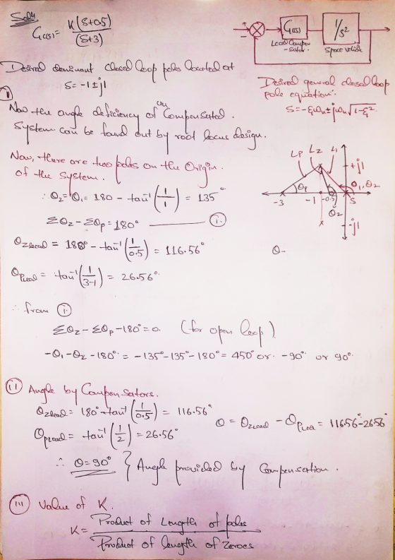
 4. A lead compensator with a transfer function Ge(s) = K(s+0.5)/(s+3) has been designed for a Space vehicle with the transfer function 1/s? such that at the dominant closed loop poles are located at -1 +/-jl. (1) What is the angle deficiency of the uncompensated system at the designed point provided by the location of the dominant poles? Show that the compensator provides the necessary lead angle at the designed point to satisfy the root locus angle criterion. (iii) What...
Consider the automobile cruise-control system shown below: Engine ActuatorCarburetor 0.833 and load 40 3s +1 Compensator R(s)E(s) Ge(s) s +1 -t e(t) Sensor 0.03 1) Derive the closed-loop transfer fun...
 Consider the automobile cruise-control system shown below: Engine ActuatorCarburetor 0.833 and load 40 3s +1 Compensator R(s)E(s) Ge(s) s +1 -t e(t) Sensor 0.03 1) Derive the closed-loop transfer function of V(s)/R(s) when Gc(s)-1 2) Derive the closed-loop transfer function of E(s)/R(s) when Ge(s)-1 3) Plot the time history of the error e(t) of the closed-loop system when r(t) is a unit step input. 4) Plot the root-loci of the uncompensated system (when Gc(s)-1). Mark the closed-loop complex poles on...
A system having an open loop transfer function of G(S) = K10/(S+2)(3+1) has a root locus...
 A system having an open loop transfer function of G(S) = K10/(S+2)(3+1) has a root locus plot as shown below. The location of the roots for a system gain of K= 0.248 is show on the plot. At this location the system has a damping factor of 0.708 and a settling time of 4/1.5 = 2.67 seconds. A lead compensator is to be used to improve the transient response. (Note that nothing is plotted on the graph except for that...
Consider the sontrol system shown in the figure below: R(S) + E(s) C(s) K (s +...
 Consider the sontrol system shown in the figure below: R(S) + E(s) C(s) K (s + 4)(s + 6) g) Sketch the uncompensated system root locus showing all details. (5 Points) h) Find the dominant closed loop poles of the uncompensated system to operate with a 16.3% overshoot and peak time tp = 0.7255 (make sure to show this point on the Root Locus) (5 Points) (s+z) Now we want to design a PI compensator of the form to increase...
Q. 1 (10 marks) For the system in Fig. 1 (a) Assume proportion control. Ge(s) =...
 Q. 1 (10 marks) For the system in Fig. 1 (a) Assume proportion control. Ge(s) = K. sketch the root locus for the closed-loop system (b). Using the angle condition, prove that s1 =-2 +j2 is not on the root locus. (c). Design a lead compensator such that the dominant closed-loop poles are located at s-2tj2. (d). What are the zero and pole of lead compensator Ge(s)? (e). With Ge (s) has the zero and pole found in (c), sketch...
Question 1 (60 points) Consider the following block diagram where G(s)- Controller R(s) G(s) (a) Sketch the root locus assuming a proportional controller is used. [25 points] (b) Design specifica...
 Question 1 (60 points) Consider the following block diagram where G(s)- Controller R(s) G(s) (a) Sketch the root locus assuming a proportional controller is used. [25 points] (b) Design specifications require a closed-loop pole at (-3+j1). Design a lead compensator to make sure the root locus goes through this point. For the design, pick the pole of the compensator at-23 and analytically find its zero. (Hint: Lead compensator transfer function will be Ge (s)$+23 First plot the poles and zeros...
Q. 1 (5 marks) For the system in Fig. (a). Assume proportion control, Gc(s)-K, sketch the root lo...
 pls answer dont just copy other solution or ur catching a
dislike
Q. 1 (5 marks) For the system in Fig. (a). Assume proportion control, Gc(s)-K, sketch the root locus for the closed-loop system (b). Using the angle condition, prove that s12 +j2 is not on the root locus. (c). Design a lead compensator Ge(s) - K such that the dominant closed-loop poles are located at s1--2 2. (d), What are the zero and pole of lead compensator G() (e)....
pls answer dont just copy other solution or ur catching a
dislike
Q. 1 (5 marks) For the system in Fig. (a). Assume proportion control, Gc(s)-K, sketch the root locus for the closed-loop system (b). Using the angle condition, prove that s12 +j2 is not on the root locus. (c). Design a lead compensator Ge(s) - K such that the dominant closed-loop poles are located at s1--2 2. (d), What are the zero and pole of lead compensator G() (e)....
1 CONTROL SYSTEM ANALYSIS & DESIGN Spring 2019 HW 7 Due 4/4/2019, Thursday, 11:59pm 1. Design...
 1 CONTROL SYSTEM ANALYSIS & DESIGN Spring 2019 HW 7 Due 4/4/2019, Thursday, 11:59pm 1. Design a lead compensator for the closed-loop (CL) system whose open loop transfer function is given below. Design objectives: reduce the time constant by 50% while maintaining the same value of the damping ratio for the dominant poles. Please note that H(s)-1. Please use the method based on root locus plot. G(s) 2 [s(s+2)] Please include detailed step Obtain the location of the desired dominant...
3 .0.2) 0(z) ℉.20-1011,. +20s+101)(s+20) 20), the damping ratio for the dominant Problem 2: For a...
 3 .0.2) 0(z) ℉.20-1011,. +20s+101)(s+20) 20), the damping ratio for the dominant Problem 2: For a unity feedback system with closed loop poles is to be 0.4, and the settling time is to be 0.5 second for the compensated system. a. b. c. d. Find the coordinates of the dominant poles. Find the location of the compensator zero if the compensator pole is at -15 (lead compensator) Find the required system gain. Compare the performance of the uncompensated and compensated...
A plant with the transfer function Gp(s)-- with unity feedback has the root locus shown in the figure below: (s+2)(s+4) Root Locus 1.5 C(s) 0.5 0.5 1.5 .3 Real Axis (seconds) (a) Determine K of G...
 A plant with the transfer function Gp(s)-- with unity feedback has the root locus shown in the figure below: (s+2)(s+4) Root Locus 1.5 C(s) 0.5 0.5 1.5 .3 Real Axis (seconds) (a) Determine K of Gp(s) if it is desired that the uncompensated system has a 10% OS (overshoot) to a step input. (4 points) a 5% overshoot and a peak time Tp 3.1 meets the requirements described in part (b) and achieves zero steady state (b) Compute the desired...
 4. A lead compensator with a transfer function Ge(s) = K(s+0.5)/(s+3) has been designed for a Space vehicle with the transfer function 1/s? such that at the dominant closed loop poles are located at -1 +/-jl. (1) What is the angle deficiency of the uncompensated system at the designed point provided by the location of the dominant poles? Show that the compensator provides the necessary lead angle at the designed point to satisfy the root locus angle criterion. (iii) What...
 Consider the automobile cruise-control system shown below: Engine ActuatorCarburetor 0.833 and load 40 3s +1 Compensator R(s)E(s) Ge(s) s +1 -t e(t) Sensor 0.03 1) Derive the closed-loop transfer function of V(s)/R(s) when Gc(s)-1 2) Derive the closed-loop transfer function of E(s)/R(s) when Ge(s)-1 3) Plot the time history of the error e(t) of the closed-loop system when r(t) is a unit step input. 4) Plot the root-loci of the uncompensated system (when Gc(s)-1). Mark the closed-loop complex poles on...
 A system having an open loop transfer function of G(S) = K10/(S+2)(3+1) has a root locus plot as shown below. The location of the roots for a system gain of K= 0.248 is show on the plot. At this location the system has a damping factor of 0.708 and a settling time of 4/1.5 = 2.67 seconds. A lead compensator is to be used to improve the transient response. (Note that nothing is plotted on the graph except for that...
 Consider the sontrol system shown in the figure below: R(S) + E(s) C(s) K (s + 4)(s + 6) g) Sketch the uncompensated system root locus showing all details. (5 Points) h) Find the dominant closed loop poles of the uncompensated system to operate with a 16.3% overshoot and peak time tp = 0.7255 (make sure to show this point on the Root Locus) (5 Points) (s+z) Now we want to design a PI compensator of the form to increase...
 Q. 1 (10 marks) For the system in Fig. 1 (a) Assume proportion control. Ge(s) = K. sketch the root locus for the closed-loop system (b). Using the angle condition, prove that s1 =-2 +j2 is not on the root locus. (c). Design a lead compensator such that the dominant closed-loop poles are located at s-2tj2. (d). What are the zero and pole of lead compensator Ge(s)? (e). With Ge (s) has the zero and pole found in (c), sketch...
 Question 1 (60 points) Consider the following block diagram where G(s)- Controller R(s) G(s) (a) Sketch the root locus assuming a proportional controller is used. [25 points] (b) Design specifications require a closed-loop pole at (-3+j1). Design a lead compensator to make sure the root locus goes through this point. For the design, pick the pole of the compensator at-23 and analytically find its zero. (Hint: Lead compensator transfer function will be Ge (s)$+23 First plot the poles and zeros...
 pls answer dont just copy other solution or ur catching a
dislike
Q. 1 (5 marks) For the system in Fig. (a). Assume proportion control, Gc(s)-K, sketch the root locus for the closed-loop system (b). Using the angle condition, prove that s12 +j2 is not on the root locus. (c). Design a lead compensator Ge(s) - K such that the dominant closed-loop poles are located at s1--2 2. (d), What are the zero and pole of lead compensator G() (e)....
pls answer dont just copy other solution or ur catching a
dislike
Q. 1 (5 marks) For the system in Fig. (a). Assume proportion control, Gc(s)-K, sketch the root locus for the closed-loop system (b). Using the angle condition, prove that s12 +j2 is not on the root locus. (c). Design a lead compensator Ge(s) - K such that the dominant closed-loop poles are located at s1--2 2. (d), What are the zero and pole of lead compensator G() (e)....
 1 CONTROL SYSTEM ANALYSIS & DESIGN Spring 2019 HW 7 Due 4/4/2019, Thursday, 11:59pm 1. Design a lead compensator for the closed-loop (CL) system whose open loop transfer function is given below. Design objectives: reduce the time constant by 50% while maintaining the same value of the damping ratio for the dominant poles. Please note that H(s)-1. Please use the method based on root locus plot. G(s) 2 [s(s+2)] Please include detailed step Obtain the location of the desired dominant...
 3 .0.2) 0(z) ℉.20-1011,. +20s+101)(s+20) 20), the damping ratio for the dominant Problem 2: For a unity feedback system with closed loop poles is to be 0.4, and the settling time is to be 0.5 second for the compensated system. a. b. c. d. Find the coordinates of the dominant poles. Find the location of the compensator zero if the compensator pole is at -15 (lead compensator) Find the required system gain. Compare the performance of the uncompensated and compensated...
 A plant with the transfer function Gp(s)-- with unity feedback has the root locus shown in the figure below: (s+2)(s+4) Root Locus 1.5 C(s) 0.5 0.5 1.5 .3 Real Axis (seconds) (a) Determine K of Gp(s) if it is desired that the uncompensated system has a 10% OS (overshoot) to a step input. (4 points) a 5% overshoot and a peak time Tp 3.1 meets the requirements described in part (b) and achieves zero steady state (b) Compute the desired...
Most questions answered within 3 hours.
-
A driver travels northbound on a highway at a speed of 24.0 m/s.
A police car,...
asked 1 minute ago -
There are three things that contribute to the significance of
differences. The following is NOT one...
asked 7 minutes ago -
A glowing blackbody is at a temperature of 4.325×10³ K. For this
temperature the peak in...
asked 13 minutes ago -
Explain the reasons for enacting the Dodd-Frank Act. What are
some of the implications of this...
asked 5 minutes ago -
What do you regard as the most pressing questions HRM
should tackle? Why do you see...
asked 7 minutes ago -
The Little Coffee Company (LC) is considering entering into the
coffee-brewing business, which is dominated by...
asked 14 minutes ago -
Need help making this Java program:
package assignment1;
public class Fibonacci {
// Exercise 1: Fibonacci...
asked 56 minutes ago -
5) Suppose a price floor on sparkling wine is proposed by the
Health Minister of the...
asked 22 minutes ago -
how
are monotremes, cyanodonts , and synapsids related ?
asked 31 minutes ago -
Webster Corporation is preparing a master budget for the first
quarter of the year. The company...
asked 40 minutes ago -
Exercise Technology
The relationship of the technology ( Positive Effects ) to
society and the
world....
asked 33 minutes ago -
NEED THE SQL QUERIES ASAP PLEASE(LIKE 1 HOUR) THE ONES WITH ID
ARE PRIMARY KEYS OR...
asked 31 minutes ago