
Homework Answers
Hello,
Please find
the answer attached as under. Please give a thumbs up
rating if you find the answer useful! Have a rocking day
ahead!
The input range to your circuit is 1.617 to 1.683, which is 1.683 - 1.617 = 0.0660V. Assume that the same Vref = 3.3V is used for the ADC as well. Thus, the ADC input will accept analog inputs from 0 till 3.3V. Thus, the slope of the transfer function = 3.3/0.0660 = 50. Also the output of the circuit is 0V when the input is 1.617V. Thus, the y-offset is -50*1.617 = -80.85. Thus, the function needs to be: y = 50x - 80.85 = 50(x-1.61)
This is achieved by the circuit below:
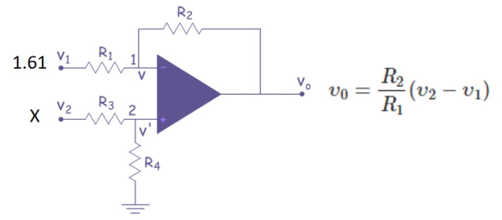
To achieve a gain of 50, R2/R1 = 50. Put R2 =50K and R1 = 1k. Also R3 = 50K and R4 = 1K
*****************************************************************
PS: Please do not forget the thumbs
up
Add Answer to:
9. Open ended design question. There is no one right answer. Design an amplifier circuit to...
Laboratory 1: operation amplifier characteristics A. Objectives: 1. To study the basic characteri...
 thanks
Laboratory 1: operation amplifier characteristics A. Objectives: 1. To study the basic characteristics of an operational amplifier 2. To study the bias circuit of an operational amplifier B. Apparatus: 1. DC Power supply 2. Experimental board and corresponding components 3. Electronic calculator (prepared by students) 4. Digital camera (prepared by students for photo taking of the experimental results) 5. Laptop computer with the software PicoScope 6 and Microsoft Word installed. 6. PicoScope PC Oscilloscope and its accessories. 7. Multimeter...
thanks
Laboratory 1: operation amplifier characteristics A. Objectives: 1. To study the basic characteristics of an operational amplifier 2. To study the bias circuit of an operational amplifier B. Apparatus: 1. DC Power supply 2. Experimental board and corresponding components 3. Electronic calculator (prepared by students) 4. Digital camera (prepared by students for photo taking of the experimental results) 5. Laptop computer with the software PicoScope 6 and Microsoft Word installed. 6. PicoScope PC Oscilloscope and its accessories. 7. Multimeter...
Question 3. Unregulated supply Rz IL Vin IR Ib (a) The circuit on the right shows...
 Question 3. Unregulated supply Rz IL Vin IR Ib (a) The circuit on the right shows a series regulator connected to the output of an unregulated power supply. The transistor has B =50, and a 6 volt Zener diode is used. When the load current, Il, is 1 amp the de input voltage from the unregulated supply, Vin, is 11 volt, VBE = 1 volt and the Zener diode current, Iz, is 20 mA. For these conditions, calculate Iz (i)...
need help for d,e,f OP-Amp Circuit R-20k Fig 1 1. Design an operational amplifier circuit using an LM741 op-amp an...
 need help for d,e,f
OP-Amp Circuit R-20k Fig 1 1. Design an operational amplifier circuit using an LM741 op-amp and a 10k the diagram shown in Fig 1 to produce the output voltage feedback resistor that represents Clearly write your ID number in Table 1 Table 1 Your ID Number 3775。73 . Set up the roquired gain numbers as follows and write them in Table 2 Ai- the last digit of your ID number+5 A2-the 2ed last digit of your...
need help for d,e,f
OP-Amp Circuit R-20k Fig 1 1. Design an operational amplifier circuit using an LM741 op-amp and a 10k the diagram shown in Fig 1 to produce the output voltage feedback resistor that represents Clearly write your ID number in Table 1 Table 1 Your ID Number 3775。73 . Set up the roquired gain numbers as follows and write them in Table 2 Ai- the last digit of your ID number+5 A2-the 2ed last digit of your...
sedra smith book 7th edition chapter name is operational amplifier. question 12.1 to 12.10 I need...
 sedra smith book 7th edition chapter name is operational
amplifier. question 12.1 to 12.10 I need all solution with good
hand writing.
Problems 1075 Transistor Q3 WIL (um/um) 36/0.3 36/0.3 6/0.3 6/0.3 30/0.3 W/0.3 45/0.3 6/0.3 and A, if all devices are 0.3 m long, Q and Q2 are operated at overdrive voltages of 0.15-V magnitude, and Q is operated at Voy 0.2 V. Also, determine the op-amp output resistance 100 k2, C0.1 pF, G = 2 mA/V, R, =...
sedra smith book 7th edition chapter name is operational
amplifier. question 12.1 to 12.10 I need all solution with good
hand writing.
Problems 1075 Transistor Q3 WIL (um/um) 36/0.3 36/0.3 6/0.3 6/0.3 30/0.3 W/0.3 45/0.3 6/0.3 and A, if all devices are 0.3 m long, Q and Q2 are operated at overdrive voltages of 0.15-V magnitude, and Q is operated at Voy 0.2 V. Also, determine the op-amp output resistance 100 k2, C0.1 pF, G = 2 mA/V, R, =...
Question 4. (a) A full-wave bridge rectifier power supply is powered from the secondary of a...
 Question 4. (a) A full-wave bridge rectifier power supply is powered from the secondary of a transformer which has a rms secondary voltage of 15.6V. The primary of the transformer is connected to a 50Hz, 230VRMS power supply. A 2700uF filter capacitor is used. A current of 1.5 Amp is drawn from the supply. (i) Sketch a schematic diagram of the setup. (ii) Calculate the mean de output voltage. Assume each power diode has a forward voltage drop of 1...
 thanks
Laboratory 1: operation amplifier characteristics A. Objectives: 1. To study the basic characteristics of an operational amplifier 2. To study the bias circuit of an operational amplifier B. Apparatus: 1. DC Power supply 2. Experimental board and corresponding components 3. Electronic calculator (prepared by students) 4. Digital camera (prepared by students for photo taking of the experimental results) 5. Laptop computer with the software PicoScope 6 and Microsoft Word installed. 6. PicoScope PC Oscilloscope and its accessories. 7. Multimeter...
thanks
Laboratory 1: operation amplifier characteristics A. Objectives: 1. To study the basic characteristics of an operational amplifier 2. To study the bias circuit of an operational amplifier B. Apparatus: 1. DC Power supply 2. Experimental board and corresponding components 3. Electronic calculator (prepared by students) 4. Digital camera (prepared by students for photo taking of the experimental results) 5. Laptop computer with the software PicoScope 6 and Microsoft Word installed. 6. PicoScope PC Oscilloscope and its accessories. 7. Multimeter...
 Question 3. Unregulated supply Rz IL Vin IR Ib (a) The circuit on the right shows a series regulator connected to the output of an unregulated power supply. The transistor has B =50, and a 6 volt Zener diode is used. When the load current, Il, is 1 amp the de input voltage from the unregulated supply, Vin, is 11 volt, VBE = 1 volt and the Zener diode current, Iz, is 20 mA. For these conditions, calculate Iz (i)...
 need help for d,e,f
OP-Amp Circuit R-20k Fig 1 1. Design an operational amplifier circuit using an LM741 op-amp and a 10k the diagram shown in Fig 1 to produce the output voltage feedback resistor that represents Clearly write your ID number in Table 1 Table 1 Your ID Number 3775。73 . Set up the roquired gain numbers as follows and write them in Table 2 Ai- the last digit of your ID number+5 A2-the 2ed last digit of your...
need help for d,e,f
OP-Amp Circuit R-20k Fig 1 1. Design an operational amplifier circuit using an LM741 op-amp and a 10k the diagram shown in Fig 1 to produce the output voltage feedback resistor that represents Clearly write your ID number in Table 1 Table 1 Your ID Number 3775。73 . Set up the roquired gain numbers as follows and write them in Table 2 Ai- the last digit of your ID number+5 A2-the 2ed last digit of your...
 sedra smith book 7th edition chapter name is operational
amplifier. question 12.1 to 12.10 I need all solution with good
hand writing.
Problems 1075 Transistor Q3 WIL (um/um) 36/0.3 36/0.3 6/0.3 6/0.3 30/0.3 W/0.3 45/0.3 6/0.3 and A, if all devices are 0.3 m long, Q and Q2 are operated at overdrive voltages of 0.15-V magnitude, and Q is operated at Voy 0.2 V. Also, determine the op-amp output resistance 100 k2, C0.1 pF, G = 2 mA/V, R, =...
sedra smith book 7th edition chapter name is operational
amplifier. question 12.1 to 12.10 I need all solution with good
hand writing.
Problems 1075 Transistor Q3 WIL (um/um) 36/0.3 36/0.3 6/0.3 6/0.3 30/0.3 W/0.3 45/0.3 6/0.3 and A, if all devices are 0.3 m long, Q and Q2 are operated at overdrive voltages of 0.15-V magnitude, and Q is operated at Voy 0.2 V. Also, determine the op-amp output resistance 100 k2, C0.1 pF, G = 2 mA/V, R, =...
 Question 4. (a) A full-wave bridge rectifier power supply is powered from the secondary of a transformer which has a rms secondary voltage of 15.6V. The primary of the transformer is connected to a 50Hz, 230VRMS power supply. A 2700uF filter capacitor is used. A current of 1.5 Amp is drawn from the supply. (i) Sketch a schematic diagram of the setup. (ii) Calculate the mean de output voltage. Assume each power diode has a forward voltage drop of 1...
Most questions answered within 3 hours.
-
I am currently taking a Foundation of Programming course where
we are being taught Java. We...
asked 18 minutes ago -
Suppose a car is traveling at +22.2 m/s, and the driver sees a
traffic light turn...
asked 8 minutes ago -
1) Write a method that will return the length of smallest string
in an array of...
asked 15 minutes ago -
Select one of the following WSJ articles and apply the type
concepts from producers and users...
asked 34 minutes ago -
Make sure you are able to describe the 3 primary goals of
seating interventions.
asked 38 minutes ago -
How does microfiltration work in industrial milk processing? is
it through pump or is it through...
asked 38 minutes ago -
A spy satellite is in circular orbit around Earth. It makes one
revolution in 7.20 h....
asked 39 minutes ago -
When sending an email from one RMU email account to another RMU
email account, the email...
asked 40 minutes ago -
When 10.0 mg of sucrose is dissolved in enough water to make
100.0 mL of solution...
asked 58 minutes ago -
I have volunteered at a butterfly garden and I am supposed to
write a journal reflection...
asked 1 hour ago -
10 Distributions of GNU Linux
10 Distributions
5 different operating Systems
What is the exact function...
asked 1 hour ago -
Two point charges are fixed on the y axis: a negative point
charge q1 = -33...
asked 1 hour ago