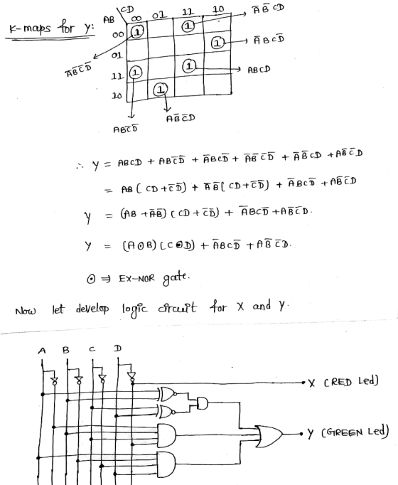
Design a Digital combinational logic circuit using logic gates that has 4 inputs and 2 outputs....
Design a Digital combinational logic circuit using
logic gates that
has 4 inputs and 2 outputs. The circuit:
i. Turns on a Red LED if its input is a multiple of 2. (i.e., 0, 2,
4, 6, 8 …..)
ii. Turns on a Green LED if its input is a multiple of 3. (i.e. 0,
3, 6, 9)
- Draw the truth table for the circuit, bearing in mind that this
circuit has 4 inputs and 2
outputs, meaning your truth table should have 16 rows and 6
columns.
-The order of the truth table columns should match the order of
your switches. Thus the
right most column of the truth table (LSB) must be the Right most
switch and similarly the
MSB must be the Left most switch.
- Draw the circuit schematic.
legend, pin numbers, resistor values etc.
Homework Answers

Add Answer to:
Design a Digital combinational logic circuit using
logic gates that
has 4 inputs and 2 outputs....
Design a combinational circuit with three inputs, x , y, and z, and three outputs, A,...
Design a combinational circuit with three inputs, x , y, and z, and three outputs, A, B , and C . When the binary input is 0, 1, 2, or 3, the binary output is one greater than the input. When the binary input is 4, 5, 6, or 7, the binary output is two less than the input. 1) Truth table 2) Logic circuit 3) Boolean function of A using minterms ( use Boolean algebra) 4) Boolean function of...
2. Design a combinational logic circuit with three inputs x, y, and z, and three outputs...
 2. Design a combinational logic circuit with three inputs x, y, and z, and three outputs A, B, and C. When the binary input value is 0, 1, 2, or 3, the binary output value is 2 greater than the input, i.e. (ABC) = (xyz) + 2. Otherwise, the binary output value is 3 less than the input, i.e. (ABC) = (xyz) – 3.
Digital design question. Combinational logic & building blocks. 9.1 Voting circuit. Using combinational building blocks such...
 Digital design question.
Combinational logic & building blocks.
9.1 Voting circuit. Using combinational building blocks such as adders, comparators, mul- tiplexers, decoders, encoders, and arbiters, as well as logic gates, design a circuit that accepts five three-bit one-hot numbers and outputs the three-bit one-hot number that occurred most often on the inputs. Ties can be broken in any manner. For example, if the inputs are 100, 100, 100, 010, and 001, the output will be 100
Digital design question.
Combinational logic & building blocks.
9.1 Voting circuit. Using combinational building blocks such as adders, comparators, mul- tiplexers, decoders, encoders, and arbiters, as well as logic gates, design a circuit that accepts five three-bit one-hot numbers and outputs the three-bit one-hot number that occurred most often on the inputs. Ties can be broken in any manner. For example, if the inputs are 100, 100, 100, 010, and 001, the output will be 100
DESIGN SECTION You are going to design which has 4 inputs wi L V. and 4...
 DESIGN SECTION You are going to design which has 4 inputs wi L V. and 4 outputs A, B.Cand D. The features of the circuit are; a combinational eircuit Inputs (w, x, y, z) Binary Code Outputs (A, B, C, DGray Code The circuit encodes Input Bit Sequence (Binary Code) to Gray Code. You are going to; a) Fill the truth table according to your design. b) Find the simplified AND-OR expressions for all 4 outputs (Sum of Product) by...
Design the logic circuit to display a 3 bit octal numbers from 0 to 7 on...
 Design the logic circuit to display a 3 bit octal numbers from 0 to 7 on a seven segment display shown below (for number 1 use segments b and c; for 6 include segment (a) Write the Truth Table with A, B. C representing the input bits (A is the MSB) and a, b, c, d, e, f and g representing the outputs to the seven segments. (b) Implement the circuit using a Programmable Logic Array (use simplified notation to...
Why can't we design a combinational digital logic circuit to control a light so that the...
Why can't we design a combinational digital logic circuit to control a light so that the light changes state any time its "push-button" switch is pressed? (Press and release the button, and the light changes state. Press and release again, and the light changes state again.) Try to list as many properties this circuit needs to have that we cannot model as you can! Reminder: a "combinational digital logic circuit" takes one or more boolean inputs and feeds them through...
Design a combinational circuit that adds 1 to 3-bit unsigned binary number and produces an unsigned...
 Design a combinational circuit that adds 1 to 3-bit unsigned binary number and produces an unsigned binary result. Do the following: (1) determine the number of inputs/outputs, (2) write the truth table, (3) simplify the output functions by using maps and (4) draw the logic diagram by using AND OR and NOT gates. Show the truth table, the map, and the logic diagram. Do NOT use adders.
Design a combinational circuit which inputs a three-bit binary number, and outputs the input number PLUS...
Design a combinational circuit which inputs a three-bit binary number, and outputs the input number PLUS two if the input is less then or equal to 3, and outputs the minus two if the input is greater than 3. This should include the truth table for the operation, the karnaugh map(s), and the resulting circuit.
For this problem, you are to design a simple combinational logic circuit The circuit is a...
For this problem, you are to design a simple combinational logic circuit The circuit is a 2- bit priority encoder with inputs I2 and I1 and outputs Z1 and Z0. The circuit behaves as follows: • If I2I1 = 00, then Z1Z0 = 00 (no active input) • If I2I1 = 01, then Z1Z0 = 01 (low-priority input, X1, is active) • If I2I1 = 1-, then Z1Z0 = 10 (high-priority input, X2, is active) Note that...
Title: Combinational Circuit Design and Simulation Objectives: a. b. c. Design combinational circuit Verify design with...
 Title: Combinational Circuit Design and Simulation Objectives: a. b. c. Design combinational circuit Verify design with simulation Verify design with laboratory test data Materials Needed IBM Compatible computer, PSpice software, IC Chips (as needed), Data Switches, 4702 (1), LED (1). Pre-Lab: Problem Statement The four parameters in a chemical process control system to be monitored are temperature (T), pressure (P), flow (F), and level (L) of the fluid. The parameters are monitored by sensor circuits that produce a High logic...
 2. Design a combinational logic circuit with three inputs x, y, and z, and three outputs A, B, and C. When the binary input value is 0, 1, 2, or 3, the binary output value is 2 greater than the input, i.e. (ABC) = (xyz) + 2. Otherwise, the binary output value is 3 less than the input, i.e. (ABC) = (xyz) – 3.
 Digital design question.
Combinational logic & building blocks.
9.1 Voting circuit. Using combinational building blocks such as adders, comparators, mul- tiplexers, decoders, encoders, and arbiters, as well as logic gates, design a circuit that accepts five three-bit one-hot numbers and outputs the three-bit one-hot number that occurred most often on the inputs. Ties can be broken in any manner. For example, if the inputs are 100, 100, 100, 010, and 001, the output will be 100
Digital design question.
Combinational logic & building blocks.
9.1 Voting circuit. Using combinational building blocks such as adders, comparators, mul- tiplexers, decoders, encoders, and arbiters, as well as logic gates, design a circuit that accepts five three-bit one-hot numbers and outputs the three-bit one-hot number that occurred most often on the inputs. Ties can be broken in any manner. For example, if the inputs are 100, 100, 100, 010, and 001, the output will be 100
 DESIGN SECTION You are going to design which has 4 inputs wi L V. and 4 outputs A, B.Cand D. The features of the circuit are; a combinational eircuit Inputs (w, x, y, z) Binary Code Outputs (A, B, C, DGray Code The circuit encodes Input Bit Sequence (Binary Code) to Gray Code. You are going to; a) Fill the truth table according to your design. b) Find the simplified AND-OR expressions for all 4 outputs (Sum of Product) by...
 Design the logic circuit to display a 3 bit octal numbers from 0 to 7 on a seven segment display shown below (for number 1 use segments b and c; for 6 include segment (a) Write the Truth Table with A, B. C representing the input bits (A is the MSB) and a, b, c, d, e, f and g representing the outputs to the seven segments. (b) Implement the circuit using a Programmable Logic Array (use simplified notation to...
 Design a combinational circuit that adds 1 to 3-bit unsigned binary number and produces an unsigned binary result. Do the following: (1) determine the number of inputs/outputs, (2) write the truth table, (3) simplify the output functions by using maps and (4) draw the logic diagram by using AND OR and NOT gates. Show the truth table, the map, and the logic diagram. Do NOT use adders.
 Title: Combinational Circuit Design and Simulation Objectives: a. b. c. Design combinational circuit Verify design with simulation Verify design with laboratory test data Materials Needed IBM Compatible computer, PSpice software, IC Chips (as needed), Data Switches, 4702 (1), LED (1). Pre-Lab: Problem Statement The four parameters in a chemical process control system to be monitored are temperature (T), pressure (P), flow (F), and level (L) of the fluid. The parameters are monitored by sensor circuits that produce a High logic...
Most questions answered within 3 hours.
-
Why did the observed chemistry of thallium mislead Mendelev to
place the group 13 element (Tl)...
asked 47 minutes ago -
A sine wave signal is displayed on the screen of an
oscilloscope. 6 peak-to-peak divisions are...
asked 3 hours ago -
a
1500 kg car accelerates from 0 to 25 m / s in 21.0s. How much...
asked 4 hours ago -
Calculate the molarity of each of the following solutions:
(a) 30.5 g of ethanol (C2H5OH) in...
asked 4 hours ago -
1 Refer to the build-borrow-or-buy framework as a decision tree
for the Adidas company. Identify a...
asked 4 hours ago -
Problem 2: The Problem of Social Cost. A Rancher and Farmer live
side-by-side to each other....
asked 6 hours ago -
a uniform bar of weight 40N is 4 meter long. weights
on 60N and 100N are...
asked 5 hours ago -
Define Diet counceling? What are the
responsibilities of a counselor?
asked 7 hours ago -
Hey im just confused about how to put the ' A angle n' and ' S...
asked 7 hours ago -
A short essay about the WSJ article on Oreo versus Hydrox.
asked 7 hours ago -
##8. A program contains the following function definition:
##def cube(num):
##return num * num * num...
asked 7 hours ago -
find the value z of a standard Normal variable that satisfies
each of the given conditions....
asked 8 hours ago