
Homework Answers
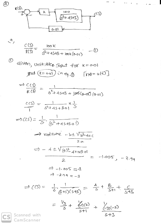
![-|Cit)= §.ult) Pķe ult)+ sie tych) ¢ from Given unit step input fork=001 Iritsault)] R15 = 005)_ 100(0:1) $4+45+3 + 100(0.1)](http://img.homeworklib.com/questions/b0d90250-196d-11ec-b275-d964a2c9e6ac.png?x-oss-process=image/resize,w_560)

![(P+D] 34+45+3 0.01 RIS _CCS! 100(S ) St4s+3 + 10oCoreD CAS) RIS) 10o CS+) STAS+3+(145) - 10015+) +GS) = 100(+1) S +45+3 -993-](http://img.homeworklib.com/questions/b3668470-196d-11ec-8018-d91258aa2740.png?x-oss-process=image/resize,w_560)
Add Answer to:
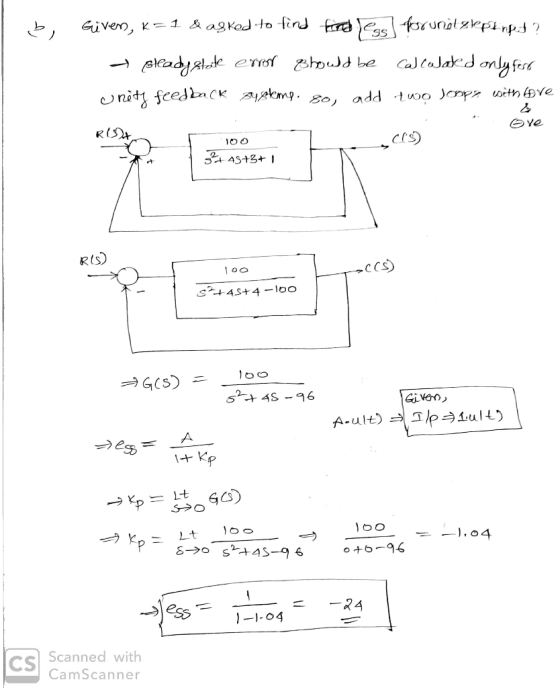
Question 4: Consider the following system: 0.01 a) Describe the response to a unit step input...
Question 2 Consider the system shown in Figure Q2, where Wis a unit step disturbance and R is a unit step input. 0.4 s+ 1 10 Figure Q2 (5 marks) (3 marks) (c) Find the value for K so that the steady...
 Question 2 Consider the system shown in Figure Q2, where Wis a unit step disturbance and R is a unit step input. 0.4 s+ 1 10 Figure Q2 (5 marks) (3 marks) (c) Find the value for K so that the steady state error due to w(t) is less than 0.01; 6 marks) (d) In order to eliminate the steady state error, show whether a PI controller can be successful 6 marks) (a) Find the expression of E(s)-R(s)-Y(s) in terms...
Problem 4. Consider the control system shown below with plant G(s) that has time con- stants...
 Problem 4. Consider the control system shown below with plant G(s) that has time con- stants T1 = 2, T2 = 10, and gain k = 0.1. 4 673 +1679+1) (1.) Sketch the pole-zero plot for G(s). Is one of the poles more dominant? Using MATLAB, simulate the step response of the plant itself, along with G1(s) and G2(s) as defined by Gl(s) = and G2(s) = sti + 1 ST2+1 (2.) Design a proportional gain C(s) = K so...
1. A feedback control system is shown in the figure below. Suppose that our design objective...
 1. A feedback control system is shown in the figure below. Suppose that our design objective is to find a controller Gc(S) of minimal complexity such that our closed-loop system can track a unit step input with a steady-state error of zero. (b) Now consider a more complex controller Gc(S) = [ Ko + K//s] where Ko = 2 and Ki = 20. (This is a proportional + integral (PI) controller). Plot the unit step response, and determine the steady-state...
Consider the closed loop system defined by the following block diagram. a) Compute the transfer function...
 Consider the closed loop system defined by the following block diagram. a) Compute the transfer function E(s)/R(s). b) Determine the steady state error for a unit-step 1. Controller ant Itly Ro- +- HI- 4단Toy , c) d) e) reference input signal. Determine the steady state error response for a unit-ramp reference input signal. Determine the locations of the closed loop poles of the system. Select system parameters kp and ki in terms of k so that damping coefficient V2/2 and...
Consider a unity-feedback control system with a PI controller Gpr(s) and a plant G(s) in cascade. In particular, the plant transfer function is given as 2. G(s) = s+4, and the PI controller trans...
 Consider a unity-feedback control system with a PI controller Gpr(s) and a plant G(s) in cascade. In particular, the plant transfer function is given as 2. G(s) = s+4, and the PI controller transfer function is of the forrm KI p and Ki are the proportional and integral controller gains, respectively where K Design numerical values for Kp and Ki such that the closed-loop control system has a step- response settling time T, 0.5 seconds with a damping ratio of...
PROBLEM 4 Suppose that a system is shown in Figure 4. There are three controllers that might be incorporated into this system. 1. Ge (s)-K (proportional (P) controller) 2. GS)K/s (integral (I) contro...
 PROBLEM 4 Suppose that a system is shown in Figure 4. There are three controllers that might be incorporated into this system. 1. Ge (s)-K (proportional (P) controller) 2. GS)K/s (integral (I) controller) 3. G (s)K(1+1/s) (proportional, integral (PI) controller) The system requirements are T, < 10 seconds and P0 10% for a unit step response. (a) For the (P) controller, write a piece of MATLAB code to plot root locus for 0<K<,and find the K value so that the...
A unity feedback system with the forward transfer function G(s)=K/(s+1)(s+3)(s+6) is operating wi...
 A unity feedback system with the forward transfer function
G(s)=K/(s+1)(s+3)(s+6) is operating with a closed-loop step
response that has 15% overshoot. Do the following:
a) Evaluate the steady-state error for a unit step input
b) Design a PI control to reduce the steady-state error to zero
without affecting its transient response
c) Evaluate the steady-state error and overshoot for a unit step
input to your compensated system
A unity feedback system with the forward transfer function G(s) is operating with...
A unity feedback system with the forward transfer function
G(s)=K/(s+1)(s+3)(s+6) is operating with a closed-loop step
response that has 15% overshoot. Do the following:
a) Evaluate the steady-state error for a unit step input
b) Design a PI control to reduce the steady-state error to zero
without affecting its transient response
c) Evaluate the steady-state error and overshoot for a unit step
input to your compensated system
A unity feedback system with the forward transfer function G(s) is operating with...
1. Consider a unity feedback control system with the transfer function G(s) = 1/[s(s+ 2)] in...
1. Consider a unity feedback control system with the transfer function G(s) = 1/[s(s+ 2)] in the forward path. (a) Design a proportional controller that yields a stable system with percent overshoot less that 5% for the step input (b) Find settling time and peak time of the closed-loop system designed in part (a); (c) Design a PD compensator that reduces the settling time computed in (b) by a factor of 4 while keeping the percent overshoot less that 5%...
Please wriite the matlab code of the question
 &&&&&&&&&&&&&&&&&&&&&&&&&&&&&&&
Please wriite the matlab code of the question :)))
&&&&&&&&&&&&&&&&&&&&&&&&&&&&&&&
PROBLEM 4 Suppose that a system is shown in Figure 4. There are three controllers that might be incorporated into this system. 1·G,(s)-K (proportional (P) controller) 2·G,(s)=K/s (integral (I) controller) 3. G (s) K(1+1/s) (proportional, integral (PI) controller) The system requirements are Ts < 10 seconds and P.。. 10% for a unit step response. (a) For the (P) controller, write a piece of MATLAB code to plot root locus...
&&&&&&&&&&&&&&&&&&&&&&&&&&&&&&&
Please wriite the matlab code of the question :)))
&&&&&&&&&&&&&&&&&&&&&&&&&&&&&&&
PROBLEM 4 Suppose that a system is shown in Figure 4. There are three controllers that might be incorporated into this system. 1·G,(s)-K (proportional (P) controller) 2·G,(s)=K/s (integral (I) controller) 3. G (s) K(1+1/s) (proportional, integral (PI) controller) The system requirements are Ts < 10 seconds and P.。. 10% for a unit step response. (a) For the (P) controller, write a piece of MATLAB code to plot root locus...
 Question 2 Consider the system shown in Figure Q2, where Wis a unit step disturbance and R is a unit step input. 0.4 s+ 1 10 Figure Q2 (5 marks) (3 marks) (c) Find the value for K so that the steady state error due to w(t) is less than 0.01; 6 marks) (d) In order to eliminate the steady state error, show whether a PI controller can be successful 6 marks) (a) Find the expression of E(s)-R(s)-Y(s) in terms...
 Question 2 Consider the system shown in Figure Q2, where Wis a unit step disturbance and R is a unit step input. 0.4 s+ 1 10 Figure Q2 (5 marks) (3 marks) (c) Find the value for K so that the steady state error due to w(t) is less than 0.01; 6 marks) (d) In order to eliminate the steady state error, show whether a PI controller can be successful 6 marks) (a) Find the expression of E(s)-R(s)-Y(s) in terms...
 Problem 4. Consider the control system shown below with plant G(s) that has time con- stants T1 = 2, T2 = 10, and gain k = 0.1. 4 673 +1679+1) (1.) Sketch the pole-zero plot for G(s). Is one of the poles more dominant? Using MATLAB, simulate the step response of the plant itself, along with G1(s) and G2(s) as defined by Gl(s) = and G2(s) = sti + 1 ST2+1 (2.) Design a proportional gain C(s) = K so...
 1. A feedback control system is shown in the figure below. Suppose that our design objective is to find a controller Gc(S) of minimal complexity such that our closed-loop system can track a unit step input with a steady-state error of zero. (b) Now consider a more complex controller Gc(S) = [ Ko + K//s] where Ko = 2 and Ki = 20. (This is a proportional + integral (PI) controller). Plot the unit step response, and determine the steady-state...
 Consider the closed loop system defined by the following block diagram. a) Compute the transfer function E(s)/R(s). b) Determine the steady state error for a unit-step 1. Controller ant Itly Ro- +- HI- 4단Toy , c) d) e) reference input signal. Determine the steady state error response for a unit-ramp reference input signal. Determine the locations of the closed loop poles of the system. Select system parameters kp and ki in terms of k so that damping coefficient V2/2 and...
 Consider a unity-feedback control system with a PI controller Gpr(s) and a plant G(s) in cascade. In particular, the plant transfer function is given as 2. G(s) = s+4, and the PI controller transfer function is of the forrm KI p and Ki are the proportional and integral controller gains, respectively where K Design numerical values for Kp and Ki such that the closed-loop control system has a step- response settling time T, 0.5 seconds with a damping ratio of...
 PROBLEM 4 Suppose that a system is shown in Figure 4. There are three controllers that might be incorporated into this system. 1. Ge (s)-K (proportional (P) controller) 2. GS)K/s (integral (I) controller) 3. G (s)K(1+1/s) (proportional, integral (PI) controller) The system requirements are T, < 10 seconds and P0 10% for a unit step response. (a) For the (P) controller, write a piece of MATLAB code to plot root locus for 0<K<,and find the K value so that the...
 A unity feedback system with the forward transfer function
G(s)=K/(s+1)(s+3)(s+6) is operating with a closed-loop step
response that has 15% overshoot. Do the following:
a) Evaluate the steady-state error for a unit step input
b) Design a PI control to reduce the steady-state error to zero
without affecting its transient response
c) Evaluate the steady-state error and overshoot for a unit step
input to your compensated system
A unity feedback system with the forward transfer function G(s) is operating with...
A unity feedback system with the forward transfer function
G(s)=K/(s+1)(s+3)(s+6) is operating with a closed-loop step
response that has 15% overshoot. Do the following:
a) Evaluate the steady-state error for a unit step input
b) Design a PI control to reduce the steady-state error to zero
without affecting its transient response
c) Evaluate the steady-state error and overshoot for a unit step
input to your compensated system
A unity feedback system with the forward transfer function G(s) is operating with...
 &&&&&&&&&&&&&&&&&&&&&&&&&&&&&&&
Please wriite the matlab code of the question :)))
&&&&&&&&&&&&&&&&&&&&&&&&&&&&&&&
PROBLEM 4 Suppose that a system is shown in Figure 4. There are three controllers that might be incorporated into this system. 1·G,(s)-K (proportional (P) controller) 2·G,(s)=K/s (integral (I) controller) 3. G (s) K(1+1/s) (proportional, integral (PI) controller) The system requirements are Ts < 10 seconds and P.。. 10% for a unit step response. (a) For the (P) controller, write a piece of MATLAB code to plot root locus...
&&&&&&&&&&&&&&&&&&&&&&&&&&&&&&&
Please wriite the matlab code of the question :)))
&&&&&&&&&&&&&&&&&&&&&&&&&&&&&&&
PROBLEM 4 Suppose that a system is shown in Figure 4. There are three controllers that might be incorporated into this system. 1·G,(s)-K (proportional (P) controller) 2·G,(s)=K/s (integral (I) controller) 3. G (s) K(1+1/s) (proportional, integral (PI) controller) The system requirements are Ts < 10 seconds and P.。. 10% for a unit step response. (a) For the (P) controller, write a piece of MATLAB code to plot root locus...
Most questions answered within 3 hours.
-
5. Suppose you obtained 0.55 g of crude clove oil from 7.0 g of
fresh cloves....
asked 6 minutes ago -
Provide a paragraph of introduction that generally describes
cognitive development over the lifespan.
asked 10 minutes ago -
In a market, when the price increased the total expenditure on
the good also increased. Is...
asked 10 minutes ago -
If 5.70 g of potassium react with water, how many grams of
hydrogen gas, H2, are...
asked 24 minutes ago -
How many moles of CO2 and H2O will be
produced by combustion analysis of 0.010 mol...
asked 22 minutes ago -
Tennis champion Maria Sharapova is capable of serving a tennis
ball at 126 mph.
b) What...
asked 30 minutes ago -
The electric potential V in the space between the plates of a
given vacuum tube is...
asked 40 minutes ago -
The Hydroboration-Oxidation of an Alkene to Yield 1-Octanol.
1-octene to 1-octanol using BH3-THF
What might be...
asked 45 minutes ago -
You draw and keep a single bill from a hat that contains a
$11, $55, $20...
asked 1 hour ago -
Write a Java program that has the following methods:
findSum - a method that takes in...
asked 1 hour ago -
A coffee cup calorimeter initially contains 135g of water at
22.0oC. Calcium chloride (21.0g) at the...
asked 1 hour ago -
A patient is having a magnetic resonance imaging scan (an MRI)
and has neglected to remove...
asked 1 hour ago