
Homework Answers

Add Answer to:
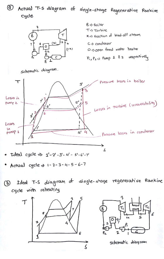
(2) (a) Draw the ACTUAL T-s diagram of a 'single-stage regenerative cycle? (5 points) (b) Draw...
Please draw T-S and P-V diagrams relevant to the DGEN380 engine cycle identifying the actual stat...
 please
draw T-S and P-V diagrams relevant to the DGEN380 engine cycle
identifying the actual station numbering ( not to scale )
ral Information the following engine section numbering: Retale 4145 S 25 Fig3.1: Engine Section Numbering Location Station Number Front Fan Face 21 Gooseneck Inlet Compressor Inlet Diffuser Exit Combustion Chamber Exit HP Turbine Inlet HP Turbine Exit LP Turbine Inlet LP Turbine Exit Core Stream Exit Fan Stream Exit 25 41 45 18 Table3.I: Section Numbering Identification Draw...
please
draw T-S and P-V diagrams relevant to the DGEN380 engine cycle
identifying the actual station numbering ( not to scale )
ral Information the following engine section numbering: Retale 4145 S 25 Fig3.1: Engine Section Numbering Location Station Number Front Fan Face 21 Gooseneck Inlet Compressor Inlet Diffuser Exit Combustion Chamber Exit HP Turbine Inlet HP Turbine Exit LP Turbine Inlet LP Turbine Exit Core Stream Exit Fan Stream Exit 25 41 45 18 Table3.I: Section Numbering Identification Draw...
3) For the regenerative cycle shown in the figure determine per kg of steam: a. Draw...
 3) For the regenerative cycle shown in the figure determine per kg of steam: a. Draw T-s diagram showing the cycle points b. The mass flux of steam extracted from the turbine c. The cycle thermal efficiency Boiler 10 MPa 600 °C Turbine Turbine € 20 MW - 20 MW 1000 kPa Closed focdwater heater 10 kPa a Condenser Condensate pump
A regenerative Rankin cycle utilized the schematic of the figure below. 1. A regenerative Rankine cycle...
 A regenerative Rankin cycle utilized the schematic of the figure
below.
1. A regenerative Rankine cycle utilized the schematic of the figure below. . Conditions: T1-450oC, P1-3 MPa, T2-2500C, P,-0.4 MPa, T-150oC, P,-0.1 MPa, P.-0.01 MPa, T,-140°C,H,-592k/kg.npump=0.8 Boiler/ Superheate 6 Condenser 10 Pump (a.) Determine the pressures for streams 5, 6, 8,9, and 10 in MPa (b.) Determine m/m, (c.) Determine the enthalpies of streams 5 and 6 in kJ/kg. (d.) Determine the efficiency of turbine stage (e.) Determine the...
A regenerative Rankin cycle utilized the schematic of the figure
below.
1. A regenerative Rankine cycle utilized the schematic of the figure below. . Conditions: T1-450oC, P1-3 MPa, T2-2500C, P,-0.4 MPa, T-150oC, P,-0.1 MPa, P.-0.01 MPa, T,-140°C,H,-592k/kg.npump=0.8 Boiler/ Superheate 6 Condenser 10 Pump (a.) Determine the pressures for streams 5, 6, 8,9, and 10 in MPa (b.) Determine m/m, (c.) Determine the enthalpies of streams 5 and 6 in kJ/kg. (d.) Determine the efficiency of turbine stage (e.) Determine the...
3: Consider the Rankine power cycle using vapor and liquid. a: Explain what kinds of problems the Carnot Vapor Cycle has. b: Draw a T-s diagram for the ideal Rankine cycle and label each process...
 3: Consider the Rankine power cycle using vapor and liquid. a: Explain what kinds of problems the Carnot Vapor Cycle has. b: Draw a T-s diagram for the ideal Rankine cycle and label each process explicitly c: There is a method to lower the condenser pressure (or to decrease the average low temperature) in order to improve the efficiency of the ideal Rankine cycle. Explain its advantages and disadvantages explicitly. d: Name the gas power cycle which uses the same...
WWVUU moressar Q-1 A power plant operates on a regenerative vapor power cycle with one closed...
 WWVUU moressar Q-1 A power plant operates on a regenerative vapor power cycle with one closed feedwater heater. Steam (water vapor) enters the first turbine stage at 120 bar, 520°C and expands to 10 bar, where some of the steam is extracted and diverted to a closed feedwater heater. Condensate exiting the feedwater heater as saturated liquid at 10 bar (State 7) passes through a trap (valve) into the condenser. The feedwater exits the heater at 120 bar with a...
please use Rankine cycle. write the solution clearly 5. (25 points) Consider an ideal steam regenerative...
 please use Rankine cycle. write the solution clearly
5. (25 points) Consider an ideal steam regenerative Rankine cycle in which steam enters the turbine at 3.0 MPa, 400°C, and exhausts to the condenser at 10 kPa. Steam is extracted from the turbine at 0.8 MPa for an open feedwater heater. The feedwater leaves the heater as saturated liquid. The appropriate pumps are used for the water leaving the condenser and the feedwater heater. Calculate the thermal efficiency of the cycle...
please use Rankine cycle. write the solution clearly
5. (25 points) Consider an ideal steam regenerative Rankine cycle in which steam enters the turbine at 3.0 MPa, 400°C, and exhausts to the condenser at 10 kPa. Steam is extracted from the turbine at 0.8 MPa for an open feedwater heater. The feedwater leaves the heater as saturated liquid. The appropriate pumps are used for the water leaving the condenser and the feedwater heater. Calculate the thermal efficiency of the cycle...
A refrigerator is constructed with a Carnot engine. Draw a diagram of the Carnot cycle in...
 A refrigerator is constructed with a Carnot engine. Draw a diagram of the Carnot cycle in a P-V diagram, label the components, and then detail the processes that occur (I short phrase each is all that is necessary). Draw a diagram of the Carnot cycle in a H-S diagram, and label it to match (a) Note: His enthalpy and S is entropy. Water is brought to 0 °C in the refrigerator with the heat being discharged into a reservoir at...
4. A regenerative two-stage gas turbine with reheat operating on the standard-air Brayton cycle i...
 4. A regenerative two-stage gas turbine with reheat operating on
the standard-air Brayton cycle is illustrated in Figure 3. In an
ideal Brayton cycle, the processes in the turbines and compressor
are adiabatic and isentropic, and the air flows through the
combustor and heat exchangers at constant pressure.
a) Show that the maximum total work output is
developed when the pressure ratio is the same across each stage, if
the temperature at the inlet to each turbine stage is the...
4. A regenerative two-stage gas turbine with reheat operating on
the standard-air Brayton cycle is illustrated in Figure 3. In an
ideal Brayton cycle, the processes in the turbines and compressor
are adiabatic and isentropic, and the air flows through the
combustor and heat exchangers at constant pressure.
a) Show that the maximum total work output is
developed when the pressure ratio is the same across each stage, if
the temperature at the inlet to each turbine stage is the...
5-6 Figure 5-6 shows the schematic diagram for a two-stage cascade refrigeration system. Each stage operates...
 5-6 Figure 5-6 shows the schematic diagram for a two-stage cascade refrigeration system. Each stage operates on an ideal vapor-compression refrigeration cycle with refrigerant- 134a as the working fluid. All the important data and refrigerant phases are given in the schematic diagrams. By referring to the diagrams, determine: (a) The ratio of mass flow rate of the system and draw a T-s diagram complete with the data given. Enthalpy values for each states. Compressor power input for Cycle A and...
b) A steam regenerative cycle, shown below, is delivering 100 MW of power. Steam from the...
 b) A steam regenerative cycle, shown below, is delivering 100 MW of power. Steam from the boiler is supplied to the turbine at 8 MPa, 400°C. After expanding isentropically in the 1st stage turbine to a pressure of 1 MPa, steam is taken to the reheater where its temperature is raised back to 400°C and supplied to the 2nd stage turbine. Expansion in the 2nd stage turbine is also isentropic to a pressure of 400 kPa, where a fraction (y...
 please
draw T-S and P-V diagrams relevant to the DGEN380 engine cycle
identifying the actual station numbering ( not to scale )
ral Information the following engine section numbering: Retale 4145 S 25 Fig3.1: Engine Section Numbering Location Station Number Front Fan Face 21 Gooseneck Inlet Compressor Inlet Diffuser Exit Combustion Chamber Exit HP Turbine Inlet HP Turbine Exit LP Turbine Inlet LP Turbine Exit Core Stream Exit Fan Stream Exit 25 41 45 18 Table3.I: Section Numbering Identification Draw...
please
draw T-S and P-V diagrams relevant to the DGEN380 engine cycle
identifying the actual station numbering ( not to scale )
ral Information the following engine section numbering: Retale 4145 S 25 Fig3.1: Engine Section Numbering Location Station Number Front Fan Face 21 Gooseneck Inlet Compressor Inlet Diffuser Exit Combustion Chamber Exit HP Turbine Inlet HP Turbine Exit LP Turbine Inlet LP Turbine Exit Core Stream Exit Fan Stream Exit 25 41 45 18 Table3.I: Section Numbering Identification Draw...
 3) For the regenerative cycle shown in the figure determine per kg of steam: a. Draw T-s diagram showing the cycle points b. The mass flux of steam extracted from the turbine c. The cycle thermal efficiency Boiler 10 MPa 600 °C Turbine Turbine € 20 MW - 20 MW 1000 kPa Closed focdwater heater 10 kPa a Condenser Condensate pump
 A regenerative Rankin cycle utilized the schematic of the figure
below.
1. A regenerative Rankine cycle utilized the schematic of the figure below. . Conditions: T1-450oC, P1-3 MPa, T2-2500C, P,-0.4 MPa, T-150oC, P,-0.1 MPa, P.-0.01 MPa, T,-140°C,H,-592k/kg.npump=0.8 Boiler/ Superheate 6 Condenser 10 Pump (a.) Determine the pressures for streams 5, 6, 8,9, and 10 in MPa (b.) Determine m/m, (c.) Determine the enthalpies of streams 5 and 6 in kJ/kg. (d.) Determine the efficiency of turbine stage (e.) Determine the...
A regenerative Rankin cycle utilized the schematic of the figure
below.
1. A regenerative Rankine cycle utilized the schematic of the figure below. . Conditions: T1-450oC, P1-3 MPa, T2-2500C, P,-0.4 MPa, T-150oC, P,-0.1 MPa, P.-0.01 MPa, T,-140°C,H,-592k/kg.npump=0.8 Boiler/ Superheate 6 Condenser 10 Pump (a.) Determine the pressures for streams 5, 6, 8,9, and 10 in MPa (b.) Determine m/m, (c.) Determine the enthalpies of streams 5 and 6 in kJ/kg. (d.) Determine the efficiency of turbine stage (e.) Determine the...
 3: Consider the Rankine power cycle using vapor and liquid. a: Explain what kinds of problems the Carnot Vapor Cycle has. b: Draw a T-s diagram for the ideal Rankine cycle and label each process explicitly c: There is a method to lower the condenser pressure (or to decrease the average low temperature) in order to improve the efficiency of the ideal Rankine cycle. Explain its advantages and disadvantages explicitly. d: Name the gas power cycle which uses the same...
 WWVUU moressar Q-1 A power plant operates on a regenerative vapor power cycle with one closed feedwater heater. Steam (water vapor) enters the first turbine stage at 120 bar, 520°C and expands to 10 bar, where some of the steam is extracted and diverted to a closed feedwater heater. Condensate exiting the feedwater heater as saturated liquid at 10 bar (State 7) passes through a trap (valve) into the condenser. The feedwater exits the heater at 120 bar with a...
 please use Rankine cycle. write the solution clearly
5. (25 points) Consider an ideal steam regenerative Rankine cycle in which steam enters the turbine at 3.0 MPa, 400°C, and exhausts to the condenser at 10 kPa. Steam is extracted from the turbine at 0.8 MPa for an open feedwater heater. The feedwater leaves the heater as saturated liquid. The appropriate pumps are used for the water leaving the condenser and the feedwater heater. Calculate the thermal efficiency of the cycle...
please use Rankine cycle. write the solution clearly
5. (25 points) Consider an ideal steam regenerative Rankine cycle in which steam enters the turbine at 3.0 MPa, 400°C, and exhausts to the condenser at 10 kPa. Steam is extracted from the turbine at 0.8 MPa for an open feedwater heater. The feedwater leaves the heater as saturated liquid. The appropriate pumps are used for the water leaving the condenser and the feedwater heater. Calculate the thermal efficiency of the cycle...
 A refrigerator is constructed with a Carnot engine. Draw a diagram of the Carnot cycle in a P-V diagram, label the components, and then detail the processes that occur (I short phrase each is all that is necessary). Draw a diagram of the Carnot cycle in a H-S diagram, and label it to match (a) Note: His enthalpy and S is entropy. Water is brought to 0 °C in the refrigerator with the heat being discharged into a reservoir at...
 4. A regenerative two-stage gas turbine with reheat operating on
the standard-air Brayton cycle is illustrated in Figure 3. In an
ideal Brayton cycle, the processes in the turbines and compressor
are adiabatic and isentropic, and the air flows through the
combustor and heat exchangers at constant pressure.
a) Show that the maximum total work output is
developed when the pressure ratio is the same across each stage, if
the temperature at the inlet to each turbine stage is the...
4. A regenerative two-stage gas turbine with reheat operating on
the standard-air Brayton cycle is illustrated in Figure 3. In an
ideal Brayton cycle, the processes in the turbines and compressor
are adiabatic and isentropic, and the air flows through the
combustor and heat exchangers at constant pressure.
a) Show that the maximum total work output is
developed when the pressure ratio is the same across each stage, if
the temperature at the inlet to each turbine stage is the...
 5-6 Figure 5-6 shows the schematic diagram for a two-stage cascade refrigeration system. Each stage operates on an ideal vapor-compression refrigeration cycle with refrigerant- 134a as the working fluid. All the important data and refrigerant phases are given in the schematic diagrams. By referring to the diagrams, determine: (a) The ratio of mass flow rate of the system and draw a T-s diagram complete with the data given. Enthalpy values for each states. Compressor power input for Cycle A and...
 b) A steam regenerative cycle, shown below, is delivering 100 MW of power. Steam from the boiler is supplied to the turbine at 8 MPa, 400°C. After expanding isentropically in the 1st stage turbine to a pressure of 1 MPa, steam is taken to the reheater where its temperature is raised back to 400°C and supplied to the 2nd stage turbine. Expansion in the 2nd stage turbine is also isentropic to a pressure of 400 kPa, where a fraction (y...
Most questions answered within 3 hours.
-
Let X be a continuous random variable whose PDF is Let X be a
continuous random...
asked 4 minutes ago -
Martinez Company’s relevant range of production is 7,500 units
to 12,500 units. When it produces and...
asked 2 minutes ago -
A football with a mass of 1.2 kg is kicked from ground level to
a height...
asked 7 minutes ago -
Remember: Changes in supply determinants shift supply, and
changes in demand determinants shift demand. We say...
asked 6 minutes ago -
Why is the answer b), for this question? I came up with C) for
my incorrect...
asked 12 minutes ago -
Suppose that you know that in the population of full-time
employees in the United States, the...
asked 34 minutes ago -
This experiment was designed originally to sample various meat and carcass quality
aspects of Ontario pigs...
asked 35 minutes ago -
Dopamine Hydrochloride: draw the structure And Show the
functional groups in different colors and label the...
asked 27 minutes ago -
A rope supports a 10 kg dumbbell hanging from it. What is the
tension in the...
asked 26 minutes ago -
) Raw materials are studied for contamination. Suppose that
the number of particles of contamination per...
asked 49 minutes ago -
After running a regression analysis we calculated an F test and
the significance level was 0.15....
asked 44 minutes ago -
----Can someone please help me solve this one using JAVA
----I thank you in advance
Create...
asked 49 minutes ago