
Homework Answers
Answer is as follows :
According to Chegg Guidelines we are allowed to solve only first two parts i.e. A and B, so please repost others.
if there is any query please ask in comments...
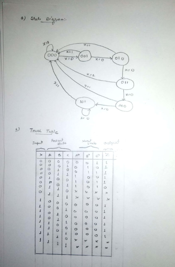
Given the State Table Below 01* 02 03 1 203 X-1 0 000 01 0 0 0 1 0 0 A. Draw a state Diagram (5 points) B. Create the "design truth table" for the "next state" and the "output"...
 Given the State Table Below 01* 02 03 1 203 X-1 0 000 01 0 0 0 1 0 0 A. Draw a state Diagram (5 points) B. Create the "design truth table" for the "next state" and the "output" (5 points) C. Make a Karnaugh for each "next state" and the "output" (10 points) When making the Karnaugh maps, "xO1" should be along the top and "0203'" along the side (The two missing states should be considered "DONT CARES")...
Given the State Table Below 01 02 Q3 X-1 A. B. C. Draw a state Diagram (S points) Create the "design truth table" for the "next state" and the "output" (5 points) Make...
 Given the State Table Below 01 02 Q3 X-1 A. B. C. Draw a state Diagram (S points) Create the "design truth table" for the "next state" and the "output" (5 points) Make a Karnaugh for each "next state" and the "output" (10 points) When making the Karnaugh maps, "xQ1" should be along the top and "O203" along the side (The two missing states should be considered "DONT CARES") Write the "Next State" and Output equations from the Karnaugh maps...
Please work on Part E & F Given the State Table Below Q1 Q2 Q3 X-1 X-0 X-1 10111loloi A. Draw a state Diagram (5 points) B. Create the "design truth table" for the "next state" an...
 Please work on Part E & F
Given the State Table Below Q1 Q2 Q3 X-1 X-0 X-1 10111loloi A. Draw a state Diagram (5 points) B. Create the "design truth table" for the "next state" and the "output"' (5 points) C. Make a Karnaugh for each "next state" and the "output" (10 points) When making the Karnaugh maps, "xQ1" should be along the top and "0203" along the side (The two missing states should be considered "DONT CARES") Write...
Please work on Part E & F
Given the State Table Below Q1 Q2 Q3 X-1 X-0 X-1 10111loloi A. Draw a state Diagram (5 points) B. Create the "design truth table" for the "next state" and the "output"' (5 points) C. Make a Karnaugh for each "next state" and the "output" (10 points) When making the Karnaugh maps, "xQ1" should be along the top and "0203" along the side (The two missing states should be considered "DONT CARES") Write...
1) Based on the sequential circuit and answer the following questions SOV a) Write equations for...
 1) Based on the sequential circuit and answer the following questions SOV a) Write equations for J, K, T, and Z in terms of the input X and the current state given by flip flop outputs QA, QB b) Based on these equations and the properties of JK and Toggle FF's fill out the state table CURRENT NEVT STATE OUTPUT QA QB X- O X=1 X-OX=1 QAQB QAQB 0 0 STATE NEXT STATE OUTPUT c) Based on the State table...
4. For the following state table 00 11 01 01 00 1 1 01 11 jus Design the system using a T flip flop for q, and an SR flip flop for the equations for the flip flop inputs and the output. 4. F...
 4. For the following state table 00 11 01 01 00 1 1 01 11 jus Design the system using a T flip flop for q, and an SR flip flop for the equations for the flip flop inputs and the output.
4. For the following state table 00 11 01 01 00 1 1 01 11 jus Design the system using a T flip flop for q, and an SR flip flop for the equations for the flip flop...
4. For the following state table 00 11 01 01 00 1 1 01 11 jus Design the system using a T flip flop for q, and an SR flip flop for the equations for the flip flop inputs and the output.
4. For the following state table 00 11 01 01 00 1 1 01 11 jus Design the system using a T flip flop for q, and an SR flip flop for the equations for the flip flop...
please, Teacher, help me with this question step by step please and explain everything, my Teacher?...
 please, Teacher, help me with this question step by step please
and explain everything, my Teacher?
EENG 250 Lab 4 M&N Flip Flop Intorduction: There are four types of latches or flip flop designs that are commonly used in designs. However it is always possible to create a custom design. For example take the JK Flip Flop. It can be built using a D Flip Flop. This can be done using state diagram design processes. As shown in the example...
please, Teacher, help me with this question step by step please
and explain everything, my Teacher?
EENG 250 Lab 4 M&N Flip Flop Intorduction: There are four types of latches or flip flop designs that are commonly used in designs. However it is always possible to create a custom design. For example take the JK Flip Flop. It can be built using a D Flip Flop. This can be done using state diagram design processes. As shown in the example...
A combination circuit is specified by the following Boolean functions listed below. h(a, b, c) = b,c' + a'c Implement the circuit with a 3x8 decoder. Provide truth table and drawing the l...
 A combination circuit is specified by the following Boolean functions listed below. h(a, b, c) = b,c' + a'c Implement the circuit with a 3x8 decoder. Provide truth table and drawing the logic/circuit diagram. Use the block diagram for the decoder provided in Figure A4 in supplements. Please label the inputs and outputs clearly. Note: use single 3x8 decoder Question 2 (15 points] A priority encoder is an encoder circuit that includes the Truth Table of a priority function. The...
1.) You have been handed a state diagram that you have been asked to implement the design for. (Unused states: extra state encodings can be treated as "don't care" values and are use...
 1.) You have been handed a state diagram that you have been asked to implement the design for. (Unused states: extra state encodings can be treated as "don't care" values and are used to simplify the combinational logic.) Next State State Name 01 State Name 020+1) 010+1) Oo+1) a. Implement the design using T flip-flops, JK flip-flops, and SR flip-flops b. Determine the Boolean expression for the inputs of the different types of flip-flops and the output.
1.) You have...
1.) You have been handed a state diagram that you have been asked to implement the design for. (Unused states: extra state encodings can be treated as "don't care" values and are used to simplify the combinational logic.) Next State State Name 01 State Name 020+1) 010+1) Oo+1) a. Implement the design using T flip-flops, JK flip-flops, and SR flip-flops b. Determine the Boolean expression for the inputs of the different types of flip-flops and the output.
1.) You have...
1) For the following state table, design the system using SR flip flops. 0 0 1 10 01 10 11 0o 01 0
 1) For the following state table, design the system using SR flip flops. 0 0 1 10 01 10 11 0o 01 0
1) For the following state table, design the system using SR flip flops. 0 0 1 10 01 10 11 0o 01 0
1) For the following state table, design the system using SR flip flops. 0 0 1 10 01 10 11 0o 01 0
ECE 260 HW 7 NAME 1. A sequential circuit has two JK flip-flops A and B,...
 ECE 260 HW 7 NAME 1. A sequential circuit has two JK flip-flops A and B, two inputs X and Y, and one output Z. The flip-flop input equations and circuit output equation are: (a) Draw the sequential circuit (b) Derive the state equations for Q and Q (c) Construct the state/output table (d) Draw the state diagram Note, for JK flip-flop: Q1O+KQ Design a sequential circuit with two JK flip-flops A and B and two inputs E and F....
 Given the State Table Below 01* 02 03 1 203 X-1 0 000 01 0 0 0 1 0 0 A. Draw a state Diagram (5 points) B. Create the "design truth table" for the "next state" and the "output" (5 points) C. Make a Karnaugh for each "next state" and the "output" (10 points) When making the Karnaugh maps, "xO1" should be along the top and "0203'" along the side (The two missing states should be considered "DONT CARES")...
 Given the State Table Below 01 02 Q3 X-1 A. B. C. Draw a state Diagram (S points) Create the "design truth table" for the "next state" and the "output" (5 points) Make a Karnaugh for each "next state" and the "output" (10 points) When making the Karnaugh maps, "xQ1" should be along the top and "O203" along the side (The two missing states should be considered "DONT CARES") Write the "Next State" and Output equations from the Karnaugh maps...
 Please work on Part E & F
Given the State Table Below Q1 Q2 Q3 X-1 X-0 X-1 10111loloi A. Draw a state Diagram (5 points) B. Create the "design truth table" for the "next state" and the "output"' (5 points) C. Make a Karnaugh for each "next state" and the "output" (10 points) When making the Karnaugh maps, "xQ1" should be along the top and "0203" along the side (The two missing states should be considered "DONT CARES") Write...
Please work on Part E & F
Given the State Table Below Q1 Q2 Q3 X-1 X-0 X-1 10111loloi A. Draw a state Diagram (5 points) B. Create the "design truth table" for the "next state" and the "output"' (5 points) C. Make a Karnaugh for each "next state" and the "output" (10 points) When making the Karnaugh maps, "xQ1" should be along the top and "0203" along the side (The two missing states should be considered "DONT CARES") Write...
 1) Based on the sequential circuit and answer the following questions SOV a) Write equations for J, K, T, and Z in terms of the input X and the current state given by flip flop outputs QA, QB b) Based on these equations and the properties of JK and Toggle FF's fill out the state table CURRENT NEVT STATE OUTPUT QA QB X- O X=1 X-OX=1 QAQB QAQB 0 0 STATE NEXT STATE OUTPUT c) Based on the State table...
 4. For the following state table 00 11 01 01 00 1 1 01 11 jus Design the system using a T flip flop for q, and an SR flip flop for the equations for the flip flop inputs and the output.
4. For the following state table 00 11 01 01 00 1 1 01 11 jus Design the system using a T flip flop for q, and an SR flip flop for the equations for the flip flop...
4. For the following state table 00 11 01 01 00 1 1 01 11 jus Design the system using a T flip flop for q, and an SR flip flop for the equations for the flip flop inputs and the output.
4. For the following state table 00 11 01 01 00 1 1 01 11 jus Design the system using a T flip flop for q, and an SR flip flop for the equations for the flip flop...
 please, Teacher, help me with this question step by step please
and explain everything, my Teacher?
EENG 250 Lab 4 M&N Flip Flop Intorduction: There are four types of latches or flip flop designs that are commonly used in designs. However it is always possible to create a custom design. For example take the JK Flip Flop. It can be built using a D Flip Flop. This can be done using state diagram design processes. As shown in the example...
please, Teacher, help me with this question step by step please
and explain everything, my Teacher?
EENG 250 Lab 4 M&N Flip Flop Intorduction: There are four types of latches or flip flop designs that are commonly used in designs. However it is always possible to create a custom design. For example take the JK Flip Flop. It can be built using a D Flip Flop. This can be done using state diagram design processes. As shown in the example...
 A combination circuit is specified by the following Boolean functions listed below. h(a, b, c) = b,c' + a'c Implement the circuit with a 3x8 decoder. Provide truth table and drawing the logic/circuit diagram. Use the block diagram for the decoder provided in Figure A4 in supplements. Please label the inputs and outputs clearly. Note: use single 3x8 decoder Question 2 (15 points] A priority encoder is an encoder circuit that includes the Truth Table of a priority function. The...
 1.) You have been handed a state diagram that you have been asked to implement the design for. (Unused states: extra state encodings can be treated as "don't care" values and are used to simplify the combinational logic.) Next State State Name 01 State Name 020+1) 010+1) Oo+1) a. Implement the design using T flip-flops, JK flip-flops, and SR flip-flops b. Determine the Boolean expression for the inputs of the different types of flip-flops and the output.
1.) You have...
1.) You have been handed a state diagram that you have been asked to implement the design for. (Unused states: extra state encodings can be treated as "don't care" values and are used to simplify the combinational logic.) Next State State Name 01 State Name 020+1) 010+1) Oo+1) a. Implement the design using T flip-flops, JK flip-flops, and SR flip-flops b. Determine the Boolean expression for the inputs of the different types of flip-flops and the output.
1.) You have...
 1) For the following state table, design the system using SR flip flops. 0 0 1 10 01 10 11 0o 01 0
1) For the following state table, design the system using SR flip flops. 0 0 1 10 01 10 11 0o 01 0
1) For the following state table, design the system using SR flip flops. 0 0 1 10 01 10 11 0o 01 0
 ECE 260 HW 7 NAME 1. A sequential circuit has two JK flip-flops A and B, two inputs X and Y, and one output Z. The flip-flop input equations and circuit output equation are: (a) Draw the sequential circuit (b) Derive the state equations for Q and Q (c) Construct the state/output table (d) Draw the state diagram Note, for JK flip-flop: Q1O+KQ Design a sequential circuit with two JK flip-flops A and B and two inputs E and F....
Most questions answered within 3 hours.
-
Accent Software faces the following conditions. All of these
support Accent’s use of a market-penetration pricing...
asked 38 minutes ago -
A mathematically inclined friend emails you the following
instructions: "Meet me in the cafeteria the first...
asked 41 minutes ago -
A monopoly sells in two countries . The demand curves in the two
countries are p1...
asked 1 hour ago -
A .15kg rubber ball is bounced off a wall. Before hitting the
wall, the ball moves...
asked 2 hours ago -
A manufacturing company preparing to build a new plant is
considering three potential locations for it....
asked 2 hours ago -
B. If compound Y has approximately the same values of solubility
in toluene as compound X,...
asked 3 hours ago -
Oscar Inc. has inventory in Japan valued at 39,051,000 Yen one
year ago. One year ago...
asked 3 hours ago -
If Canada suffered from "fundamental disequilibrium," and its
government choose not to devalue its currency, a...
asked 3 hours ago -
4. How many input & output Key Value Pairs are passed into,
and emitted out of...
asked 3 hours ago -
Why would your heart not function well if constructed of
skeletal muscle? What is the particular...
asked 3 hours ago -
Please respond to this essay question in full essay form for
Chemistry 1102 Organic and Biochemistry:...
asked 3 hours ago -
Determine the head loss and velocity of flow in a water supply main
of 15.0 cm...
asked 3 hours ago