


Homework Answers
I have solved only the first problem. Please post one question at a time. The complete solution for the first problem is in the attachment.


Add Answer to:
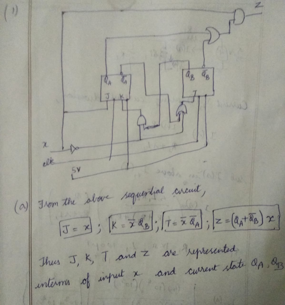
1) Based on the sequential circuit and answer the following questions SOV a) Write equations for...
Given the State Table Below 01* 02 03 1 203 X-1 0 000 01 0 0 0 1 0 0 A. Draw a state Diagram (5 points) B. Create the "design truth table" for the "next state" and the "output"...
 Given the State Table Below 01* 02 03 1 203 X-1 0 000 01 0 0 0 1 0 0 A. Draw a state Diagram (5 points) B. Create the "design truth table" for the "next state" and the "output" (5 points) C. Make a Karnaugh for each "next state" and the "output" (10 points) When making the Karnaugh maps, "xO1" should be along the top and "0203'" along the side (The two missing states should be considered "DONT CARES")...
Given the State Table Below ?" ?" X-1 AB C 0 0 0O01 0OI011 01 00...
 Given the State Table Below ?" ?" X-1 AB C 0 0 0O01 0OI011 01 00 0IOI01 1 01 01OIO0 01 A. Draw a state Diagram. B. Create the "design truth table" for the "next state" and the "output" C. Make a Karnaugh for each "next state" and the "output" When making the Karnaugh maps, "xA" should be along the top and "BC" along the side (The two missing states should be considered "DONT CARES") D. Write the "Next State"...
Given the State Table Below 01 02 Q3 X-1 A. B. C. Draw a state Diagram (S points) Create the "design truth table" for the "next state" and the "output" (5 points) Make...
 Given the State Table Below 01 02 Q3 X-1 A. B. C. Draw a state Diagram (S points) Create the "design truth table" for the "next state" and the "output" (5 points) Make a Karnaugh for each "next state" and the "output" (10 points) When making the Karnaugh maps, "xQ1" should be along the top and "O203" along the side (The two missing states should be considered "DONT CARES") Write the "Next State" and Output equations from the Karnaugh maps...
Please work on Part E & F Given the State Table Below Q1 Q2 Q3 X-1 X-0 X-1 10111loloi A. Draw a state Diagram (5 points) B. Create the "design truth table" for the "next state" an...
 Please work on Part E & F
Given the State Table Below Q1 Q2 Q3 X-1 X-0 X-1 10111loloi A. Draw a state Diagram (5 points) B. Create the "design truth table" for the "next state" and the "output"' (5 points) C. Make a Karnaugh for each "next state" and the "output" (10 points) When making the Karnaugh maps, "xQ1" should be along the top and "0203" along the side (The two missing states should be considered "DONT CARES") Write...
Please work on Part E & F
Given the State Table Below Q1 Q2 Q3 X-1 X-0 X-1 10111loloi A. Draw a state Diagram (5 points) B. Create the "design truth table" for the "next state" and the "output"' (5 points) C. Make a Karnaugh for each "next state" and the "output" (10 points) When making the Karnaugh maps, "xQ1" should be along the top and "0203" along the side (The two missing states should be considered "DONT CARES") Write...
Digital Logic Design Need help with homework. Also need to create Logisim circuit with results. T...
 Digital Logic Design
Need help with homework.
Also need to create Logisim circuit with results.
Thank you!
Your IDs gn project, spring semester Your name 19 Digital Logic Design. Mid-semester desi This is a synchronous counter design. Tables and Karnaugh maps are provided. Do this alone, do not consult with friends except for general structions guidance-I want to see your design. Design, Synchronous counter. (#2 of 3) (repeat). That is QdQcQbQa-0001 (one), 0010 (t Note: Qa is the I.s.b. Design...
Digital Logic Design
Need help with homework.
Also need to create Logisim circuit with results.
Thank you!
Your IDs gn project, spring semester Your name 19 Digital Logic Design. Mid-semester desi This is a synchronous counter design. Tables and Karnaugh maps are provided. Do this alone, do not consult with friends except for general structions guidance-I want to see your design. Design, Synchronous counter. (#2 of 3) (repeat). That is QdQcQbQa-0001 (one), 0010 (t Note: Qa is the I.s.b. Design...
Question #2. Design of a Sequential Circuit: A SEQUENCE DETECTOR that detects the sequence 10 must...
 Question #2. Design of a Sequential Circuit: A SEQUENCE DETECTOR that detects the sequence 10 must be designed whose present output z(k) is set to one when the past input u(k-1) is one and the present input u(k) is zero, where for the other three possible combinations of the input pair u(k-1), u(k) the present output z(k) is set to zero. The state diagram for a sequential circuit that detects the input sequence 10 discussed above is given below: AA...
ECE 260 HW 7 NAME 1. A sequential circuit has two JK flip-flops A and B,...
 ECE 260 HW 7 NAME 1. A sequential circuit has two JK flip-flops A and B, two inputs X and Y, and one output Z. The flip-flop input equations and circuit output equation are: (a) Draw the sequential circuit (b) Derive the state equations for Q and Q (c) Construct the state/output table (d) Draw the state diagram Note, for JK flip-flop: Q1O+KQ Design a sequential circuit with two JK flip-flops A and B and two inputs E and F....
4. For the following state table 00 11 01 01 00 1 1 01 11 jus Design the system using a T flip flop for q, and an SR flip flop for the equations for the flip flop inputs and the output. 4. F...
 4. For the following state table 00 11 01 01 00 1 1 01 11 jus Design the system using a T flip flop for q, and an SR flip flop for the equations for the flip flop inputs and the output.
4. For the following state table 00 11 01 01 00 1 1 01 11 jus Design the system using a T flip flop for q, and an SR flip flop for the equations for the flip flop...
4. For the following state table 00 11 01 01 00 1 1 01 11 jus Design the system using a T flip flop for q, and an SR flip flop for the equations for the flip flop inputs and the output.
4. For the following state table 00 11 01 01 00 1 1 01 11 jus Design the system using a T flip flop for q, and an SR flip flop for the equations for the flip flop...
Need help part B and C please. Thank you . CDA3201·Intro to Logic Desig Lab Assignment...
 Need help part B and C please. Thank you
. CDA3201·Intro to Logic Desig Lab Assignment Name: Grade: 20 5) 120] At right is the state dingram for a Moore sequential 1 01.10 АО circuit which monitors two inputs XiXo. When the two inputs XiXo are 00, the output Z toggles at every clock When the two inputs XiXo are 11, the output Z toggles at every other clock. When the two inputs XiXo are different, the output Z holds...
Need help part B and C please. Thank you
. CDA3201·Intro to Logic Desig Lab Assignment Name: Grade: 20 5) 120] At right is the state dingram for a Moore sequential 1 01.10 АО circuit which monitors two inputs XiXo. When the two inputs XiXo are 00, the output Z toggles at every clock When the two inputs XiXo are 11, the output Z toggles at every other clock. When the two inputs XiXo are different, the output Z holds...
please, Teacher, help me with this question step by step please and explain everything, my Teacher?...
 please, Teacher, help me with this question step by step please
and explain everything, my Teacher?
EENG 250 Lab 4 M&N Flip Flop Intorduction: There are four types of latches or flip flop designs that are commonly used in designs. However it is always possible to create a custom design. For example take the JK Flip Flop. It can be built using a D Flip Flop. This can be done using state diagram design processes. As shown in the example...
please, Teacher, help me with this question step by step please
and explain everything, my Teacher?
EENG 250 Lab 4 M&N Flip Flop Intorduction: There are four types of latches or flip flop designs that are commonly used in designs. However it is always possible to create a custom design. For example take the JK Flip Flop. It can be built using a D Flip Flop. This can be done using state diagram design processes. As shown in the example...
 Given the State Table Below 01* 02 03 1 203 X-1 0 000 01 0 0 0 1 0 0 A. Draw a state Diagram (5 points) B. Create the "design truth table" for the "next state" and the "output" (5 points) C. Make a Karnaugh for each "next state" and the "output" (10 points) When making the Karnaugh maps, "xO1" should be along the top and "0203'" along the side (The two missing states should be considered "DONT CARES")...
 Given the State Table Below ?" ?" X-1 AB C 0 0 0O01 0OI011 01 00 0IOI01 1 01 01OIO0 01 A. Draw a state Diagram. B. Create the "design truth table" for the "next state" and the "output" C. Make a Karnaugh for each "next state" and the "output" When making the Karnaugh maps, "xA" should be along the top and "BC" along the side (The two missing states should be considered "DONT CARES") D. Write the "Next State"...
 Given the State Table Below 01 02 Q3 X-1 A. B. C. Draw a state Diagram (S points) Create the "design truth table" for the "next state" and the "output" (5 points) Make a Karnaugh for each "next state" and the "output" (10 points) When making the Karnaugh maps, "xQ1" should be along the top and "O203" along the side (The two missing states should be considered "DONT CARES") Write the "Next State" and Output equations from the Karnaugh maps...
 Please work on Part E & F
Given the State Table Below Q1 Q2 Q3 X-1 X-0 X-1 10111loloi A. Draw a state Diagram (5 points) B. Create the "design truth table" for the "next state" and the "output"' (5 points) C. Make a Karnaugh for each "next state" and the "output" (10 points) When making the Karnaugh maps, "xQ1" should be along the top and "0203" along the side (The two missing states should be considered "DONT CARES") Write...
Please work on Part E & F
Given the State Table Below Q1 Q2 Q3 X-1 X-0 X-1 10111loloi A. Draw a state Diagram (5 points) B. Create the "design truth table" for the "next state" and the "output"' (5 points) C. Make a Karnaugh for each "next state" and the "output" (10 points) When making the Karnaugh maps, "xQ1" should be along the top and "0203" along the side (The two missing states should be considered "DONT CARES") Write...
 Digital Logic Design
Need help with homework.
Also need to create Logisim circuit with results.
Thank you!
Your IDs gn project, spring semester Your name 19 Digital Logic Design. Mid-semester desi This is a synchronous counter design. Tables and Karnaugh maps are provided. Do this alone, do not consult with friends except for general structions guidance-I want to see your design. Design, Synchronous counter. (#2 of 3) (repeat). That is QdQcQbQa-0001 (one), 0010 (t Note: Qa is the I.s.b. Design...
Digital Logic Design
Need help with homework.
Also need to create Logisim circuit with results.
Thank you!
Your IDs gn project, spring semester Your name 19 Digital Logic Design. Mid-semester desi This is a synchronous counter design. Tables and Karnaugh maps are provided. Do this alone, do not consult with friends except for general structions guidance-I want to see your design. Design, Synchronous counter. (#2 of 3) (repeat). That is QdQcQbQa-0001 (one), 0010 (t Note: Qa is the I.s.b. Design...
 Question #2. Design of a Sequential Circuit: A SEQUENCE DETECTOR that detects the sequence 10 must be designed whose present output z(k) is set to one when the past input u(k-1) is one and the present input u(k) is zero, where for the other three possible combinations of the input pair u(k-1), u(k) the present output z(k) is set to zero. The state diagram for a sequential circuit that detects the input sequence 10 discussed above is given below: AA...
 ECE 260 HW 7 NAME 1. A sequential circuit has two JK flip-flops A and B, two inputs X and Y, and one output Z. The flip-flop input equations and circuit output equation are: (a) Draw the sequential circuit (b) Derive the state equations for Q and Q (c) Construct the state/output table (d) Draw the state diagram Note, for JK flip-flop: Q1O+KQ Design a sequential circuit with two JK flip-flops A and B and two inputs E and F....
 4. For the following state table 00 11 01 01 00 1 1 01 11 jus Design the system using a T flip flop for q, and an SR flip flop for the equations for the flip flop inputs and the output.
4. For the following state table 00 11 01 01 00 1 1 01 11 jus Design the system using a T flip flop for q, and an SR flip flop for the equations for the flip flop...
4. For the following state table 00 11 01 01 00 1 1 01 11 jus Design the system using a T flip flop for q, and an SR flip flop for the equations for the flip flop inputs and the output.
4. For the following state table 00 11 01 01 00 1 1 01 11 jus Design the system using a T flip flop for q, and an SR flip flop for the equations for the flip flop...
 Need help part B and C please. Thank you
. CDA3201·Intro to Logic Desig Lab Assignment Name: Grade: 20 5) 120] At right is the state dingram for a Moore sequential 1 01.10 АО circuit which monitors two inputs XiXo. When the two inputs XiXo are 00, the output Z toggles at every clock When the two inputs XiXo are 11, the output Z toggles at every other clock. When the two inputs XiXo are different, the output Z holds...
Need help part B and C please. Thank you
. CDA3201·Intro to Logic Desig Lab Assignment Name: Grade: 20 5) 120] At right is the state dingram for a Moore sequential 1 01.10 АО circuit which monitors two inputs XiXo. When the two inputs XiXo are 00, the output Z toggles at every clock When the two inputs XiXo are 11, the output Z toggles at every other clock. When the two inputs XiXo are different, the output Z holds...
 please, Teacher, help me with this question step by step please
and explain everything, my Teacher?
EENG 250 Lab 4 M&N Flip Flop Intorduction: There are four types of latches or flip flop designs that are commonly used in designs. However it is always possible to create a custom design. For example take the JK Flip Flop. It can be built using a D Flip Flop. This can be done using state diagram design processes. As shown in the example...
please, Teacher, help me with this question step by step please
and explain everything, my Teacher?
EENG 250 Lab 4 M&N Flip Flop Intorduction: There are four types of latches or flip flop designs that are commonly used in designs. However it is always possible to create a custom design. For example take the JK Flip Flop. It can be built using a D Flip Flop. This can be done using state diagram design processes. As shown in the example...
Most questions answered within 3 hours.
-
At the beginning of the period, the Fabricating Department
budgeted direct labor of $136,500 and equipment...
asked 1 minute from now -
PARTS A-D HAVE BEEN ANSWERED. WAS TOLD TO REPOST. ONLY ANSWER
PARTS E and F.
A...
asked 16 minutes ago -
2) You are given the task of finding a representation for a
circle in a drawing...
asked 1 hour ago -
STUDY QUESTION: Does use of diet drug fen-phen
(fenfluramine-phentermine) cause valvular heart disease?
HINT: Valvular heart...
asked 1 hour ago -
1. An object weighing 40 N rests on a surface. The coefficient
of friction is 0.35....
asked 2 hours ago -
Investor company owns 35% of investee company voting stock and
accounts for the investment under the...
asked 3 hours ago -
The number of major faults on a randomly chosen 1 km stretch of
highway has a...
asked 4 hours ago -
Consider the competitive environment of Starbuck's, Progressive
Insurance, a manufacturing firm with low turnover, or a...
asked 4 hours ago -
3. Gains from trade
Consider two neighbouring island countries called Euphoria and
Contente. They each have...
asked 6 hours ago -
A business executive has the option to invest money in two
plans: Plan A guarantees that...
asked 9 hours ago -
Hello, can someone please help me answer this question?
How much heat is absorbed by a...
asked 8 hours ago -
. A marketing researcher conducted a survey of 25 shoppers
randomly selected at the local mall...
asked 9 hours ago