
Homework Answers
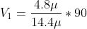
6*10^-6F and 8.4*10^-6 F are in parallel then
equivalent capacitance is (6+8.4) = 14.4
now the capacitor on right , left and equivalent capacitor are in series
total capacitance =


To find the charge we have to know the potential diffrence across the each capacitor.
as 6 and 8.4
are in parallel
so voltage across them will be equal with equivalent
capacitance.
therefore


as the capacitance is equal for other capacitor so the
voltage across them also equal with 30V
V2= 30 V
V3=30 V
therefore voltage across right , left 14.4 ,8.4 and
6 is 30 V
now charge across each capacitor as
on right and left 14.4 capacitor
are
Q14.4=14.4*30 V
 =432
=432

 =8.4*30 V
=252
 =
6*30 V
=
6*30 V
=180
Add Answer to:
Find the following. (In the figure use C1 = 14.40 MuF and C2 = 8.40 MuF.)...
Consider the following. (Let C_1 = 27.20 muF and C_2 = 21.20 muF.) (a) Find the...
 Consider the following. (Let C_1 = 27.20 muF and C_2 = 21.20 muF.) (a) Find the equivalent capacitance of the capacitors in the figure. muF (b) Find the charge on each capacitor. on the right 27.20 muF capacitor muC on the left 27.20 muF capacitor muC on the 21.20 muF capacitor muC on the 6.00 muF capacitor muC (c) Find the potential difference across each capacitor. on the right 27.20 muF capacitor V on the left 27.20 muF capacitor V...
Find the following, (in the figure use C1-32.80 μF and C2-26.80 pF.) 900 v ) the...
 Find the following, (in the figure use C1-32.80 μF and C2-26.80 pF.) 900 v ) the equivalent capacitance of the capacitors in the figure above (b) the charge on each capacitor on the right 32.80 uF capacitor on the left 32.80 μF capacitor on the 26.80 μF capaotor on the 6.00 μF capacitor (c) the potential difference across each capacitor on the right 32.80 μF capacitor on the left 32.80 μF capacitor on the 26.80 μF capacitor on the 6.00...
For the system of capacitors shown in the figure below, find the following. (Let C1 =...
 For the system of capacitors shown in the figure below, find the following. (Let C1 = 3.00 μF and C2 = 4.00 μF.) C, 6.00 μF 2.00 μF 90.0 V (a) the equivalent capacitance of the system (b) the charge on each capacitor on C1 on C2 on the 6.00 μF capacitor on the 2.00 μF capacitor με (c) the potential difference across each capacitor across C1 across C2 across the 6.00 μF capacitor across the 2.00 μF capacitor Need...
A lab tech builds a circuit as shown in the figure. Find the following. (Assume C1...
 A lab tech builds a circuit as shown in the figure. Find the following. (Assume C1 = 25.0 pF and C2 = 3.13 uF.) 6.00 pF CUF C2 uF CPF + 9.00 V (a) the equivalent capacitance (in PF) UF UC (b) the charge on each capacitor (in PC) C1 (left) C1 (right) C2 6.00 uF capacitor нс MC UC (c) the potential difference across each capacitor (in V) C (left) V C (right) V C₂ V 6.00 uF capacitor...
Consider the following. (Let C1 = 20.80 µF and C2 = 14.80 µF.) A rectangular circuit...
Consider the following. (Let C1 = 20.80 µF and C2 = 14.80 µF.) A rectangular circuit contains a battery and four capacitors. The bottom side has a 9.00 V battery with the positive terminal on the left. The left and right sides of the circuit each contain a capacitor labeled C1. The top side splits into two parallel horizontal branches, which recombine before reaching the top right corner. There is a 6.00 µF capacitor on the upper branch and a...
Consider the following. (Let C1 = 36.40 µF and C2 = 30.40 µF.) A rectangular circuit...
Consider the following. (Let C1 = 36.40 µF and C2 = 30.40 µF.) A rectangular circuit contains a battery and four capacitors. The bottom side has a 9.00 V battery with the positive terminal on the left. The left and right sides of the circuit each contain a capacitor labeled C1. The top side splits into two parallel horizontal branches, which recombine before reaching the top right corner. There is a 6.00 µF capacitor on the upper branch and a...
answer Q3 only 2. Find the following. (In the figure, use G-28.80 μF and C2-22 80mF)...
 answer Q3 only
2. Find the following. (In the figure, use G-28.80 μF and C2-22 80mF) 6.00 uF 9.00 v a) the equivalent capacitance of the capacitors in the figure above b) the charge on each capacitor on the right 28.80-uF capacitor on the left 28.80-uF capacitor on the 22.80-uF capacitor on the 6.00-uF capacitor (c) the potential difference across each capacitor on the right 28.80-uF capacitor on the left 28.80-uF capacitor on the 22.80-uF capacitor on the 6.00-uF capacitor...
answer Q3 only
2. Find the following. (In the figure, use G-28.80 μF and C2-22 80mF) 6.00 uF 9.00 v a) the equivalent capacitance of the capacitors in the figure above b) the charge on each capacitor on the right 28.80-uF capacitor on the left 28.80-uF capacitor on the 22.80-uF capacitor on the 6.00-uF capacitor (c) the potential difference across each capacitor on the right 28.80-uF capacitor on the left 28.80-uF capacitor on the 22.80-uF capacitor on the 6.00-uF capacitor...
An electrical engineer student creates a circuit as shown in the figure. Find the following. An...
 An electrical engineer student creates a circuit as shown in the
figure. Find the following.
An electrical engineering student creates a circuit as shown in the figure. Find the following. (Assume C1-34.0 μF and C2-2.93 μF.) 6.00 μF 9.00 V (a) the equivalent capacitance (in μF) 17 Did you forget to take the reciprocal to find Ced? μF (b) the charge on each capacitor (in μC) C1 (left) C1 (right) 6.00 μF capacitor (c) the potential difference across each capacitor...
An electrical engineer student creates a circuit as shown in the
figure. Find the following.
An electrical engineering student creates a circuit as shown in the figure. Find the following. (Assume C1-34.0 μF and C2-2.93 μF.) 6.00 μF 9.00 V (a) the equivalent capacitance (in μF) 17 Did you forget to take the reciprocal to find Ced? μF (b) the charge on each capacitor (in μC) C1 (left) C1 (right) 6.00 μF capacitor (c) the potential difference across each capacitor...
Two capacitors, C1 = 6.00 μF and C2 = 13.0 μF
Two capacitors, C1 = 6.00 μF and C2 = 13.0 μF, are connected in parallel, and the resulting combination is connected to a 9.00-V battery. (a) Find the equivalent capacitance of the combination. (b) Find the potential difference across each capacitor. (c) Find the charge stored on each capacitor.
An electrical engineering student creates a circuit as shown in the figure. Find the following. (Assume...
 An electrical engineering student creates a circuit as shown in the figure. Find the following. (Assume C1 = 29.0 pF and C2 = 4.03 MF.) 6.00 F CF C, F GF 9.00 V (a) the equivalent capacitance (in UF) UF (b) the charge on each capacitor (in PC) C (left) Грс C (right) Грс C₂ PC 6.00 uF capacitor C (c) the potential difference across each capacitor (in V) C (left) V (right) V C2 V 6.00 uF capacitor V
 Consider the following. (Let C_1 = 27.20 muF and C_2 = 21.20 muF.) (a) Find the equivalent capacitance of the capacitors in the figure. muF (b) Find the charge on each capacitor. on the right 27.20 muF capacitor muC on the left 27.20 muF capacitor muC on the 21.20 muF capacitor muC on the 6.00 muF capacitor muC (c) Find the potential difference across each capacitor. on the right 27.20 muF capacitor V on the left 27.20 muF capacitor V...
 Find the following, (in the figure use C1-32.80 μF and C2-26.80 pF.) 900 v ) the equivalent capacitance of the capacitors in the figure above (b) the charge on each capacitor on the right 32.80 uF capacitor on the left 32.80 μF capacitor on the 26.80 μF capaotor on the 6.00 μF capacitor (c) the potential difference across each capacitor on the right 32.80 μF capacitor on the left 32.80 μF capacitor on the 26.80 μF capacitor on the 6.00...
 For the system of capacitors shown in the figure below, find the following. (Let C1 = 3.00 μF and C2 = 4.00 μF.) C, 6.00 μF 2.00 μF 90.0 V (a) the equivalent capacitance of the system (b) the charge on each capacitor on C1 on C2 on the 6.00 μF capacitor on the 2.00 μF capacitor με (c) the potential difference across each capacitor across C1 across C2 across the 6.00 μF capacitor across the 2.00 μF capacitor Need...
 A lab tech builds a circuit as shown in the figure. Find the following. (Assume C1 = 25.0 pF and C2 = 3.13 uF.) 6.00 pF CUF C2 uF CPF + 9.00 V (a) the equivalent capacitance (in PF) UF UC (b) the charge on each capacitor (in PC) C1 (left) C1 (right) C2 6.00 uF capacitor нс MC UC (c) the potential difference across each capacitor (in V) C (left) V C (right) V C₂ V 6.00 uF capacitor...
 answer Q3 only
2. Find the following. (In the figure, use G-28.80 μF and C2-22 80mF) 6.00 uF 9.00 v a) the equivalent capacitance of the capacitors in the figure above b) the charge on each capacitor on the right 28.80-uF capacitor on the left 28.80-uF capacitor on the 22.80-uF capacitor on the 6.00-uF capacitor (c) the potential difference across each capacitor on the right 28.80-uF capacitor on the left 28.80-uF capacitor on the 22.80-uF capacitor on the 6.00-uF capacitor...
answer Q3 only
2. Find the following. (In the figure, use G-28.80 μF and C2-22 80mF) 6.00 uF 9.00 v a) the equivalent capacitance of the capacitors in the figure above b) the charge on each capacitor on the right 28.80-uF capacitor on the left 28.80-uF capacitor on the 22.80-uF capacitor on the 6.00-uF capacitor (c) the potential difference across each capacitor on the right 28.80-uF capacitor on the left 28.80-uF capacitor on the 22.80-uF capacitor on the 6.00-uF capacitor...
 An electrical engineer student creates a circuit as shown in the
figure. Find the following.
An electrical engineering student creates a circuit as shown in the figure. Find the following. (Assume C1-34.0 μF and C2-2.93 μF.) 6.00 μF 9.00 V (a) the equivalent capacitance (in μF) 17 Did you forget to take the reciprocal to find Ced? μF (b) the charge on each capacitor (in μC) C1 (left) C1 (right) 6.00 μF capacitor (c) the potential difference across each capacitor...
An electrical engineer student creates a circuit as shown in the
figure. Find the following.
An electrical engineering student creates a circuit as shown in the figure. Find the following. (Assume C1-34.0 μF and C2-2.93 μF.) 6.00 μF 9.00 V (a) the equivalent capacitance (in μF) 17 Did you forget to take the reciprocal to find Ced? μF (b) the charge on each capacitor (in μC) C1 (left) C1 (right) 6.00 μF capacitor (c) the potential difference across each capacitor...
 An electrical engineering student creates a circuit as shown in the figure. Find the following. (Assume C1 = 29.0 pF and C2 = 4.03 MF.) 6.00 F CF C, F GF 9.00 V (a) the equivalent capacitance (in UF) UF (b) the charge on each capacitor (in PC) C (left) Грс C (right) Грс C₂ PC 6.00 uF capacitor C (c) the potential difference across each capacitor (in V) C (left) V (right) V C2 V 6.00 uF capacitor V
Most questions answered within 3 hours.
-
4. How many input & output Key Value Pairs are passed into,
and emitted out of...
asked 23 minutes ago -
B. If compound Y has approximately the same values of solubility
in toluene as compound X,...
asked 12 minutes ago -
Oscar Inc. has inventory in Japan valued at 39,051,000 Yen one
year ago. One year ago...
asked 18 minutes ago -
If Canada suffered from "fundamental disequilibrium," and its
government choose not to devalue its currency, a...
asked 27 minutes ago -
Why would your heart not function well if constructed of
skeletal muscle? What is the particular...
asked 30 minutes ago -
Please respond to this essay question in full essay form for
Chemistry 1102 Organic and Biochemistry:...
asked 31 minutes ago -
Determine the head loss and velocity of flow in a water supply main
of 15.0 cm...
asked 33 minutes ago -
A marketing executive who knowingly authorizes a shoddy
defective product to be brought to market is...
asked 42 minutes ago -
Write a psudocode:
1. Define a function called authorize that takes in 2 strings,
uName, and...
asked 47 minutes ago -
What Hall voltage (in mV) is produced by a 0.180 T field applied
across a 2.60...
asked 46 minutes ago -
What mass of ethylene glycol (C2H6O2) must be added to 211.0 g
of water to obtain...
asked 48 minutes ago -
Mary's employer has a defined benefits retirement plan, which
pay 3.2% of her last year's salary...
asked 52 minutes ago