Design a power transmission mechanism with gears that converts 360 RPM to 2 RPM. The output...
Design a power transmission mechanism with gears that converts 360 RPM to 2 RPM. The output gear must have the same rotational direction as the driving gear. In your design, you need to include at least two shafts with stacked gears.
Homework Answers
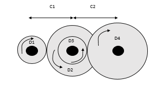
The easiest way to convert 360 rpm in 2rpm while maintaining the same rotational direction is by using a three shaft system with 4 gears as shown below (Not in scale).
The speed relation between the gear 1 and 4 is:

Where Sr1 is the speed relation between the gear 1 and 2, while Sr2 is the speed relation between gear 3 and 4. These relations can be represented by their number of teeth as follows:
Sr1 = N2/N1 and Sr2 = N4/N3
Thus:

Also, Sr can be calculated by:

Where n is the rotational speed, thus:
Sr = 360rpm/2rpm = 180
Knowing that the diametric pitch Dp= Np / Pd, where Np is the number of teeth and Pd is the pitch diameter:
We start by establishing a diametric pitch of 16 for the first reduction, and a pitch diameter of 0,5”for the gear #1. Thus the pitch diameter is:
Np1 = 16 * 0,5 = 8 Teeth
We may also establish a pitch diameter of 8”, but the diametric pitch must remain the same. Thus:
Pd2 = 20*8 = 160 teeth
Knowing this, the speed relation is:
Sr1= 160/8= 20
The speed relation between D3 and d4 must be:
Sr2=Sr/Sr1= 180/20= 9
We may use the same model of gear of the gear 1 for the gear 3, thus
Pd1 = Pd3 = 0,5”; Dp1 = Dp3 = 16 and N1 = N3 =8teeth
Thus:

N4 = 180/2,5 = 72 teeth
Since Dp4=Dp3= 16.
The Pitch diameter must be:
Dp4 = 72/16 = 4,5”
Resuming the Pitch Diameters:
D1 = 0,5”
D2 = 8”
D3 = 0,5”
D4 = 4,5”
The distance between centers is:


Add Answer to:
Design a power transmission mechanism with gears that converts
360 RPM to 2 RPM. The output...
Design a power transmission system consisting of shafts, gears, belts and bearings to run a blower...
Design a power transmission system consisting of shafts, gears, belts and bearings to run a blower and a compressor. The blower has a rated power of 5kW and weighs 100 kg while the compressor has a rated power of 10 kW and weighs 200 kg. The blower is powered by a belt drive while the compressor is powered by gear mechanism. In this exercise you have to take care of the following: Select the starting motor Design the drive shaft...
Figure Q1 shows a gear train consists of four spur gears A, B, C and D to be designed for a specific mechanism. The power transmitted by gear A is 5 kW at rotational speed of 720 rpm counterclockwise direction. Number of teeth (N) for gears A,B,C and D ar
 Figure Q1 shows a gear train consists of four spur gears A, B, C and D to be designed for a specific
mechanism. The power transmitted by gear A is 5 kW at rotational speed of 720 rpm
counterclockwise direction. Number of teeth (N) for gears A,B,C and D are respectively 20, 50,
30 and 60. The module and pressure angle of the gears are respectively 4 mm and 20o
. Determine
followings:
(a) Tangential and radial forces between gears...
Figure Q1 shows a gear train consists of four spur gears A, B, C and D to be designed for a specific
mechanism. The power transmitted by gear A is 5 kW at rotational speed of 720 rpm
counterclockwise direction. Number of teeth (N) for gears A,B,C and D are respectively 20, 50,
30 and 60. The module and pressure angle of the gears are respectively 4 mm and 20o
. Determine
followings:
(a) Tangential and radial forces between gears...
Problem 1. Design a reverted gear train for a transmission with three speeds and reverse. For...
 Problem 1. Design a reverted gear train for a transmission with three speeds and reverse. For an input speed of 450 rpm to the driving shaft (green), the driven shaft (teal) should have output forward speeds of 75, 300, and 450 rpm, and an output reverse speed of 150 rpm. Assume all gears have a diametral pitch of 10. Gear A (24 teeth) and Gear D (36 teeth) are in constant mesh. Determine the numbers of teeth for ALL six...
Design requirements: You are required to design a gear box to reduce 2,000 rpm to 90-100 rpm whil...
 ignore part 1 and 7
Design requirements: You are required to design a gear box to reduce 2,000 rpm to 90-100 rpm while transmitting a power of 18 hp. The gearbox size should be less than 15 in x 15 in base, and 20 in height and input and output shaft must be in-line. The shaft must have an infinite life, while gear and bearing life should be greater than 10,000 hours. The bearings must have a reliability of 96%....
ignore part 1 and 7
Design requirements: You are required to design a gear box to reduce 2,000 rpm to 90-100 rpm while transmitting a power of 18 hp. The gearbox size should be less than 15 in x 15 in base, and 20 in height and input and output shaft must be in-line. The shaft must have an infinite life, while gear and bearing life should be greater than 10,000 hours. The bearings must have a reliability of 96%....
Design Problem Design a speed reducer gear box that will take 1.5 kW power from an...
 Design Problem Design a speed reducer gear box that will take 1.5 kW power from an electric motor rotating at 3000 rpm (clockwise) and deliver it to a machine which operates at 2 different speeds, 1000 rpm (clockwise) and 500 rpm (counter-clockwise). Use Spur Gears with 20° pressure angle and 5mm module. Gear box should be of smallest possible size. The gear shift mechanism is not the part of the design A 2-speed double-reduction speed reducer is shown in the...
Design a speedreducer that is capable of driving two mixers at different rotational velocities. The first...
 Design a speedreducer that is capable of driving two mixers at different rotational velocities. The first mixer requires 10 kW output power, and the second one requires 5 kW output power. The first mixer shouldbe driven at 250 ± 5 rpm The second mixer should be driven at 80 ± 5 rpm. The axis ofinput and output shafts areparallel. Input shaft Gear Box Output shaft Select the type of gear set. Determine the number of teeth for each gear. ords
You are the designer and you have been asked to design a speed reducer (gearbox) that will take p...
 power = 3 kW
if need any more information please ask !!!
You are the designer and you have been asked to design a speed reducer (gearbox) that will take power from the shaft of an electric motor rotating at 1500 rpm and deliver it to a machine that is to operate at approximately at 200 rpm Assume that you have decided to use spur gears to transmit the power [A power equal to the last one digits of your...
power = 3 kW
if need any more information please ask !!!
You are the designer and you have been asked to design a speed reducer (gearbox) that will take power from the shaft of an electric motor rotating at 1500 rpm and deliver it to a machine that is to operate at approximately at 200 rpm Assume that you have decided to use spur gears to transmit the power [A power equal to the last one digits of your...
Output input 2. The gearbox in the diagram for problem 1 receives an input power of 10 kW, at a s...
 output input 2. The gearbox in the diagram for problem 1 receives an input power of 10 kW, at a speed of 40. The gears are spur gears (ignore the helix angle on the teeth in the figure), have a module of 5 mm/tooth, and the pressure angle is 20. Assume all shafts lie in the same plane. Assume the gearbox is reasonably efficient, so losses can be neglected for this analysis. (a) Determine the minimum inside dimension of the...
1: Given the power transmission system shown below Input: 30 hp, 2,000 rpm 12 pitch 18...
 1: Given the power transmission system shown below Input: 30 hp, 2,000 rpm 12 pitch 18 teeth N C Rotation Hydraulic Pump 5 hp Water Pump, 6 hp 20° pressure angle 8 pitch 20 teeth 20° pressure angle 27 teeth 40 teeth Input Pump Output Bearing (typical) p (NP) Find: A Determine the rotation direction, rotational speed, and pitch diameter of each gear Pitch Diameter (in) Rotational Speed (rpm) Gear 1333 rmp B. Determine the hp and torque in shaft...
0.2) Figure Q.2 shows a drive system in which a 20-hp electric motor drives separate output shaft...
 Desgin
0.2) Figure Q.2 shows a drive system in which a 20-hp electric motor drives separate output shafts. Gear A is mounted on the motor shafit that has a rotational spoed or 1750 rpm clockwise. Gear A drives gear train consisting of…B,C,and D thr deliver power through the shafts on which they are mounted. All gears have a diametral pitch of Pa-8.The following data are given Power delivered by gears B, C, and D: Pa Numbers of teeth for all...
Desgin
0.2) Figure Q.2 shows a drive system in which a 20-hp electric motor drives separate output shafts. Gear A is mounted on the motor shafit that has a rotational spoed or 1750 rpm clockwise. Gear A drives gear train consisting of…B,C,and D thr deliver power through the shafts on which they are mounted. All gears have a diametral pitch of Pa-8.The following data are given Power delivered by gears B, C, and D: Pa Numbers of teeth for all...
 Problem 1. Design a reverted gear train for a transmission with three speeds and reverse. For an input speed of 450 rpm to the driving shaft (green), the driven shaft (teal) should have output forward speeds of 75, 300, and 450 rpm, and an output reverse speed of 150 rpm. Assume all gears have a diametral pitch of 10. Gear A (24 teeth) and Gear D (36 teeth) are in constant mesh. Determine the numbers of teeth for ALL six...
 ignore part 1 and 7
Design requirements: You are required to design a gear box to reduce 2,000 rpm to 90-100 rpm while transmitting a power of 18 hp. The gearbox size should be less than 15 in x 15 in base, and 20 in height and input and output shaft must be in-line. The shaft must have an infinite life, while gear and bearing life should be greater than 10,000 hours. The bearings must have a reliability of 96%....
ignore part 1 and 7
Design requirements: You are required to design a gear box to reduce 2,000 rpm to 90-100 rpm while transmitting a power of 18 hp. The gearbox size should be less than 15 in x 15 in base, and 20 in height and input and output shaft must be in-line. The shaft must have an infinite life, while gear and bearing life should be greater than 10,000 hours. The bearings must have a reliability of 96%....
 Design Problem Design a speed reducer gear box that will take 1.5 kW power from an electric motor rotating at 3000 rpm (clockwise) and deliver it to a machine which operates at 2 different speeds, 1000 rpm (clockwise) and 500 rpm (counter-clockwise). Use Spur Gears with 20° pressure angle and 5mm module. Gear box should be of smallest possible size. The gear shift mechanism is not the part of the design A 2-speed double-reduction speed reducer is shown in the...
 Design a speedreducer that is capable of driving two mixers at different rotational velocities. The first mixer requires 10 kW output power, and the second one requires 5 kW output power. The first mixer shouldbe driven at 250 ± 5 rpm The second mixer should be driven at 80 ± 5 rpm. The axis ofinput and output shafts areparallel. Input shaft Gear Box Output shaft Select the type of gear set. Determine the number of teeth for each gear. ords
 power = 3 kW
if need any more information please ask !!!
You are the designer and you have been asked to design a speed reducer (gearbox) that will take power from the shaft of an electric motor rotating at 1500 rpm and deliver it to a machine that is to operate at approximately at 200 rpm Assume that you have decided to use spur gears to transmit the power [A power equal to the last one digits of your...
power = 3 kW
if need any more information please ask !!!
You are the designer and you have been asked to design a speed reducer (gearbox) that will take power from the shaft of an electric motor rotating at 1500 rpm and deliver it to a machine that is to operate at approximately at 200 rpm Assume that you have decided to use spur gears to transmit the power [A power equal to the last one digits of your...
 output input 2. The gearbox in the diagram for problem 1 receives an input power of 10 kW, at a speed of 40. The gears are spur gears (ignore the helix angle on the teeth in the figure), have a module of 5 mm/tooth, and the pressure angle is 20. Assume all shafts lie in the same plane. Assume the gearbox is reasonably efficient, so losses can be neglected for this analysis. (a) Determine the minimum inside dimension of the...
 1: Given the power transmission system shown below Input: 30 hp, 2,000 rpm 12 pitch 18 teeth N C Rotation Hydraulic Pump 5 hp Water Pump, 6 hp 20° pressure angle 8 pitch 20 teeth 20° pressure angle 27 teeth 40 teeth Input Pump Output Bearing (typical) p (NP) Find: A Determine the rotation direction, rotational speed, and pitch diameter of each gear Pitch Diameter (in) Rotational Speed (rpm) Gear 1333 rmp B. Determine the hp and torque in shaft...
 Desgin
0.2) Figure Q.2 shows a drive system in which a 20-hp electric motor drives separate output shafts. Gear A is mounted on the motor shafit that has a rotational spoed or 1750 rpm clockwise. Gear A drives gear train consisting of…B,C,and D thr deliver power through the shafts on which they are mounted. All gears have a diametral pitch of Pa-8.The following data are given Power delivered by gears B, C, and D: Pa Numbers of teeth for all...
Desgin
0.2) Figure Q.2 shows a drive system in which a 20-hp electric motor drives separate output shafts. Gear A is mounted on the motor shafit that has a rotational spoed or 1750 rpm clockwise. Gear A drives gear train consisting of…B,C,and D thr deliver power through the shafts on which they are mounted. All gears have a diametral pitch of Pa-8.The following data are given Power delivered by gears B, C, and D: Pa Numbers of teeth for all...
Most questions answered within 3 hours.
-
A laser beam is incident at an angle of 30.6° to the vertical
onto a solution...
asked 3 minutes ago -
NO VECTORS PLEASE
Start a simple Matrix template class
In this lab, you’ll be writing a...
asked 6 minutes ago -
1- What is the energy of a photon with a frequency of 7.01 ×
10¹⁴ s⁻¹?...
asked 23 minutes ago -
Cesar needs to make a decision whether to fertilize his garden
or not. His profit depends...
asked 25 minutes ago -
Illustrate the Substitution Effect, Income Effect and Total
Effect of a normal good and an inferior...
asked 24 minutes ago -
Your company has six-sigma conformance for each of 10 component
that are a part if a...
asked 38 minutes ago -
Explain the buffering components of urine, the chemical
equation, where the system is found and find...
asked 44 minutes ago -
The financial records of Leon Paul Inc. were destroyed by fire
at the end of 2017....
asked 45 minutes ago -
The normal-curve approximation can also be used for discrete
distribution other than the binomial distribution. For...
asked 1 hour ago -
1. Find the following z values for the standard normal
variable Z. (You may find it...
asked 1 hour ago -
Lakeside Motors will sell you a $9000 car for $225 a month for 60
months. What...
asked 1 hour ago -
how immigrants foster innovations and how it lead to economic
growth of the host country????
"Not...
asked 1 hour ago